What's new
What's new

round dial taper attachment

Cal Haines

Diamond
Joined
Sep 19, 2002
Location
Tucson, AZ
...
Tom- My 10EE came with a taper attachment, but it APPEARS to be missing a part-or-two. My Monarch guide, like all others of '42 MG variety, has a parts-sheet that doesn't help much ...
Dave,

Here's a couple of photos of the T/A on my '43 machine:

IMG_0686.jpg


IMG_0723.jpg


Unfortunately, my machine did not have a micrometer adjustment for the T/A. The bezel and lens for the scale and the drawbar are not shown here, but pretty much everything else is shown.

Let me know what you are interested in and I can post more photos.

Cal
 
How do the bezel and lens fit into that circular opening? I thought it would be some sort of threading and you screw it in but the inside of the circle looks smooth. My lens is in pretty bad shape. Any info on source of replacement? Thanks
 
The bezel is held in by a set screw on the back side. (You can see the hole in the second photo.) The lens rests on a lip in the bottom of the bezel and is held in (I think) by a spring clip; my spring clip seems to have gone "walk about".

My lens is plastic and in bad shape as well. A jeweler friend of mine thinks he can polish it out. I should have it back early in the week and I'll let you know how it came out.

Cal
 
The lens is just plano-convex made from acrylic. The line is cut down the center on the plano (flat) side.

I polished mine out with some Novus plastic polish and then filled the line in with some red acrylic paint. Let it dry good and hit it with wet 4000 grit sandpaper.

Unless the lens is really trashed it should be able to be cleaned up.
 
Lookie here...

Here's what I've got:

There's two bolts (one allen-head) on the cross-feed. I know they both lock the cross-feed down, but it's apparent that they have different functions... I'm not certain which of these should be locked when.

The locking bolts on the taper attachment are obvious now- unlock 'em and turn the gear-nut thing to get the taper set accordingly.

The rod sticking out on the left... I assume that's supposed to be the drawbar? is there some sort of block missing from my lathe bed? If so, where does it go, and what does it look like? If anyone has good pix of this thing, as well as dimensions that aren't readily measureable from what I have, please!!!

What the heck is Bolt #6 for? It appears to be some sort of a lock, but it doesn't seem to lock anything...
 

Attachments

  • TA controls.jpg
    TA controls.jpg
    57.2 KB · Views: 1,389
I have never seen the taper attachment flipped around like that. Guess it really dosnt matter but I would rather have the lens away from the flying swarf.

#6 is a bolt for holding on the follow rest.

The drawbar is held to the bed with the bed clamp. Miller machine makes upgraded repros:

http://www.millermachineandfabrication.com/13.htm

There is one more clamp you didnt mark On the bottom of the pic there is a clamp that holds the cross slide bar in place. You have to loosen this to use the taper attach and tighten #1. This is all in the manual.
 
Hi Dave,

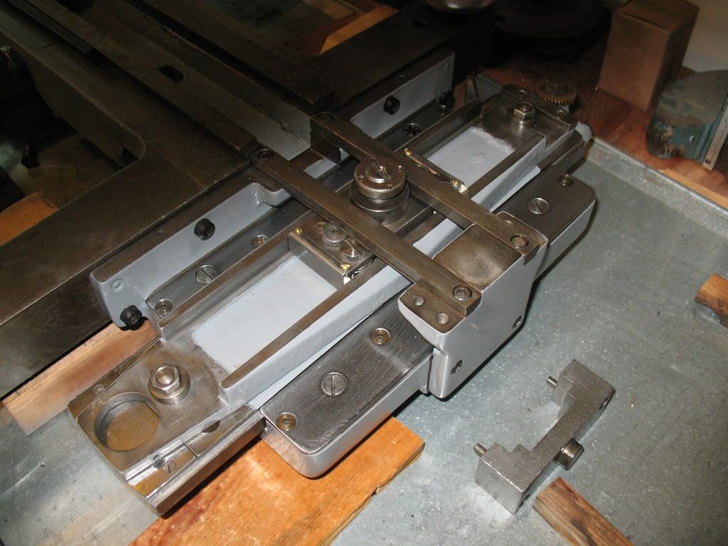
Your taper attachment looks pretty complete, with the exception of the bed clamp already mentioned. My machine is missing both the bed clamp and the draw-rod. The draw-rod unscrews from the bottom of the T/A and is normally stored when not in use.

What is the broken casting sticking out from under the T/A, right above the 'j' in "Adjustment"? I don't recognize that as being part of the machine.

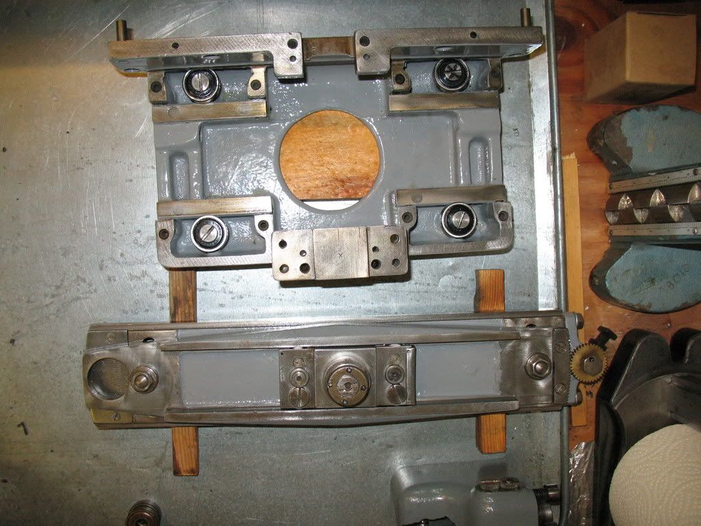
You will want to take the T/A apart and service it before you try to use it. There is no automatic lubrication for the T/A, so it needs to be taken apart and wiped down with Vactra #2 way lube every 12 months or so; much more frequently if you use coolant. There are pockets in the base casting (under each of the large bearings, in the top of my first photo) that can collect water or coolant and destroy the bearings; some folks have drilled drain holes to mitigate this. The drawbar (as opposed to the draw-rod, on top of the cross slide screw), slide, swivel and shoe, as well as the shoe stud and swivel stud, should be cleaned and lubricated. It's a good idea to clean and lube the cross slide and compound screws on the same schedule.

Cal
 
#1 clamps the cross slide screw so that it doesn't rotate when you are doing a taper cut.
#2 is what attaches the cross slide nut to the cross slide
#3 & 4 are loosened to adjust the angle of the taper.
#5 is not normal. What you have there is a portion of the micrometer gear box with just the gear that engages the rack on the TA
 
...
#5 is not normal. What you have there is a portion of the micrometer gear box with just the gear that engages the rack on the TA

Mine is the same way. The bracket appears to be designed to just carry the gear:

taper_attachment_adjuster2.jpg


Also, the manual that I have shows just the gear and bracket that I have; no micrometer adjuster.

Cal
 
That's very odd - the earliest manual I have for the 10EE (for the Sunstrand hydraulic drive) shows the vernier adjustment on the taper attachment. Heck, the 1939 patent for the 10EE shows it (patent 2,381,422).
 
Mine is the same way. The bracket appears to be designed to just carry the gear:
Hi Cal,

The micrometer adjustment has the same gear as your machine, then a second gear of identical dimension meshing to the front, then a micrometer to the front of that gear with the thimble sticking out to the rear of the lathe.

These are contained in a single assembly which mounts to the end of the TA using the same two bolts shown on your bracket.

The micrometer is reference item 485 in Figure 2 of the 1939 patent (2,381,422) mentioned by rke[pler. The whole micrometer assembly is shown in lurid detail in Figure 48 on page 30 of that document.

Details of the magnifying lens are shown in Figures 49 and 50 on page 31. The lens is a plano-convex, 1" diameter, center thickness 0.25" maximum. There's a protective cover (glass/plastic/?) over it, held in place by an O-ring.

You can download the patent for free from www.pat2pdf.org (NOT pat2pdf.com, which charges for same).

- Leigh
 
That's very odd - the earliest manual I have for the 10EE (for the Sunstrand hydraulic drive) shows the vernier adjustment on the taper attachment. Heck, the 1939 patent for the 10EE shows it (patent 2,381,422).
It looks original. There's at least two of them... Maybe it was an option at some point.

Cal, could you post the manual page?

Cal & Dave, what serial number are your machines?

-Dave
 
I just noticed a difference between Cal's TA adjustment and my micrometer version.

Cal's gear has a large hex drive, apparently designed for adjustment using a wrench.

My gear at that position has a flat round disk, perhaps 1/8" tall, holding the gear in place. There's no provision for turning either of the gears directly.
 
I have a copy of the manual for EE-16315, which someone here sent me years ago. The title page says "Revised August 1, 1942".

The 1942 manual posted by Charles Ping has the same illustration, parts picture E-9, on page 22 of the PDF file: http://bbssystem.com/viewtopic.php?t=1507

Does anyone have a photo of the micrometer adjuster on a round-dial taper attachment?

My machine is s/n 24315, built 11-1943, apparently near the very end of round-dial 10EE production.

The gear and the hex bolt are seperate pieces. The hole in the top of the hex is an oil hole.

Cal


Back
Top