What's new
What's new

New set of levers

DaveE907

Titanium
Joined
Sep 18, 2007
Location
Spanish Springs, NV
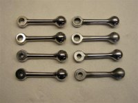
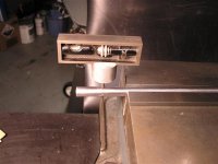
Recently completed a set of levers for an ELSR equipped 10EE. Made them from stainless steel to the pattern of the originals as close as they could be measured. The originals aren't very uniformly shaped so I used an average of the set of four shapes to dimension the new ones.

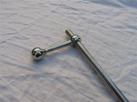
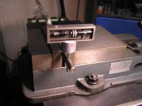
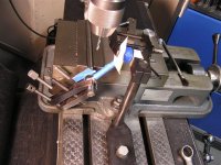
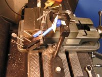
Didn't want to put new taper pin holes through their mating shafts so each new pin hole was aligned with the existing hole in the lever's mating shaft. As the original taper pin holes were all both offset from the shaft centerline and not perpendicular it was a careful setup for each one to drill the holes through the new levers. Proper clocking and axial position of the new lever must be achieved also.

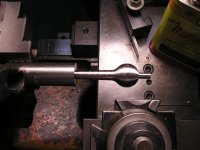
The original pins were #1 and seated to maximum diameter so to achieve a good fit the holes were reamed to #2 taper pin size and new pins fitted.

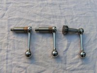
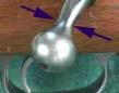
Here are some photos of the new and old levers and the completed fitted levers.
 

Attachments

  • Monarch 10 EE 3-07-B 076 (Small).jpg
    Monarch 10 EE 3-07-B 076 (Small).jpg
    43.4 KB · Views: 343
  • Monarch 10 EE 3-07-B 085 (Small).jpg
    Monarch 10 EE 3-07-B 085 (Small).jpg
    55.2 KB · Views: 271
  • Monarch 10 EE 3-07-B 093 (Small).jpg
    Monarch 10 EE 3-07-B 093 (Small).jpg
    54.7 KB · Views: 299
Dave: Another outstanding job. Now what kind of trick did you use to drill an offset hole to align correctly?
I'LL send an Email.

Hal
 
Great ! I suppose you made measurements on fixed intervals, could you post the list of measurements ?
 
No trick to setting up to make the hole in the new lever but it takes a bit of care. Some photos are included to help this explaination. The general procedure is to plumb the reamer, indicate the reamer to the spindle centerline, pin the old handle to the shaft to orient tooling to hold the new handle at the correct clocking and axial position, remove the old lever, fixture the new handle in position, spot for the new hole, drill the hole and then taper ream for the new pin maintaining the clamped up shaft and new lever in position.

First off, this was done in a level turret mill (0.0005 in./ft) so level is used as a reference for setup. The correct size taper reamer was used as an alignment aid and inserted snugly into the existing hole in the shaft the new lever will be fitted to. A simple tool was made with a faced off end and a reamed close fitting hole in the other end which fits the cylindrical end of the reamer with minimal clearance. A small level was then used to plumb the reamer in both directions utilizing the tool on the reamer body. The old handle was pinned to the shaft and an adjustable fixture was set up to hold the handle in that clocking. The old handle was removed and the new handle was positioned for both proper axial location and clocking. It was then clamped in place using cardboard to protect the surface of the new handle and the hole was spotted and drilled. The new hole was taper reamed in this set up to achieve the correct handle position when the new pin was fitted.

The photos show the ELSR lever being done. Note the position of the shaft relative to the vise jaws in the second photo, it clearly shows the angle the old pin hole is relative to perpendicular. The hole was also offset from the shaft center. The short shafts were done similarly but a 5C collet block was used to hold the shafts instead of gripping them directly in the vise.

These levers were made by step turning to generate the convex, concave and tapered shapes. Over 300 increments of axial position and diameter were calculated from the dimensions chosen to define the lever and then these carriage positions and diameters are used to make each part. It sounds worse than it is, it's faster than many would guess. The last photo shows one about half turned just after it was positioned further out in the chuck to turn the second half. The diameters were roughed out prior to cutting the final profile to speed the process along. The .25 in. spud was used in the polishing process and was parted off later stepping to create a spherical end which was then polished.
 

Attachments

  • Monarch 10 EE 3-07-B 078 (Small).jpg
    Monarch 10 EE 3-07-B 078 (Small).jpg
    44.8 KB · Views: 302
  • Monarch 10 EE 3-07-B 080 (Small).jpg
    Monarch 10 EE 3-07-B 080 (Small).jpg
    42.3 KB · Views: 303
  • Monarch 10 EE 3-07-B 082 (Small).jpg
    Monarch 10 EE 3-07-B 082 (Small).jpg
    62.4 KB · Views: 318
  • Monarch 10 EE 3-07-B 083 (Small).jpg
    Monarch 10 EE 3-07-B 083 (Small).jpg
    61.9 KB · Views: 324
  • Monarch 10 EE 3-07-B 061 (Small).jpg
    Monarch 10 EE 3-07-B 061 (Small).jpg
    48.6 KB · Views: 347
Last edited:
Me too Donie, most of the jobs I do leave the shop, machine parts and tools stick around a long time. Some tools made long ago during apprentice days are still used often and bring back good memories.
 
Thanks for the short tutorial on how you fit the handles to the existing holes in the shafts. I need to fabricate a new control lever for my machine and had noticed that all my pins appear to be at somewhat variable angles also....it wasn't keeping me up at night but I wasn't exactly looking forward to the task either.

very simple, elegant solution.


cheers,
Sean
 
Dave,

When you drill the hole for the taper pin, do you use a drill the size of the small end of the pin, or use a series of drill sizes to rough out the taper?

Cal
 
Cal, for the first through drill I used a drill a few thousands smaller than the exit hole in the old lever. Then, only the close side of the lever was drilled with a drill slightly smaller than the entrance hole in the shaft being careful not to drill deeper than just through the side of the lever. Avoid removing any material from the shaft hole until taper reaming the assembly.
 
It may be heretical, but I think if I had to make new levers for my EEs, I would make them out of SS, alright, but I would make the handle portion a good duplicate of the pre-1964 Winchester Model 70 operating bolt.

I really liked that shape. Sort of pear shaped. I wouldn't duplicate the hole in the end, though.
 
Great idea Peter! :cheers:

I share your appreciation of that classic's shape, in fact have more time with that bolt handle type than working a 10EE lever. Wish I'd thought of it, that shape would be no more trouble to produce either.
 
Here's the knob highlighted.

The arrows indicate the narrowest portion of the operating bolt.

This is an oblique view.

An end view would show that the knob is round, and that is has a hole drilled into it.

A view along the axis of the knob would show that it is pear shaped, an has a flat top to clear scopes.

The basic pear shaped knob is a classic, and was made from the thirties until the sixties.

Competitive products are spherical, or are an oblate spheroid, often with knurling.

The M70 bolt feels quite natural "in the hand", almost as if the hand itself was designed for the M70, and not the other way around.
 

Attachments

  • M70_Bolt_Knob.jpg
    M70_Bolt_Knob.jpg
    5.7 KB · Views: 186


Back
Top