Cal Haines
Diamond
- Joined
- Sep 19, 2002
- Location
- Tucson, AZ
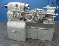
FinishCut already alerted us to this machine, but I thought that it was unusual enough to merit it’s own thread. It was sold by Reliable Tool on eBay for $2500. It’s a VERY interesting machine on several levels. For one thing, it’s the youngest round-dial I’ve seen to date. It was built in July of ’45; the prior record holder was EE26988, built in March of ’45.
MONARCH 12.5" X 20" 10EE TOOL ROOM LATHE | eBay
It also has more options that I’ve seen before:
I had forgotten that the accumulating cross-feed dial was even available on round-dials and I didn’t recall seeing an accumulating carriage feed dial “in the wild”. Neither option is listed in the 1944 round-dial brochure. Going back through my photos I did find 8 or 9 other round-dials with an accumulating cross-feed dials. I also found a photo of an accumulating carriage dial, but it was on a square dial.
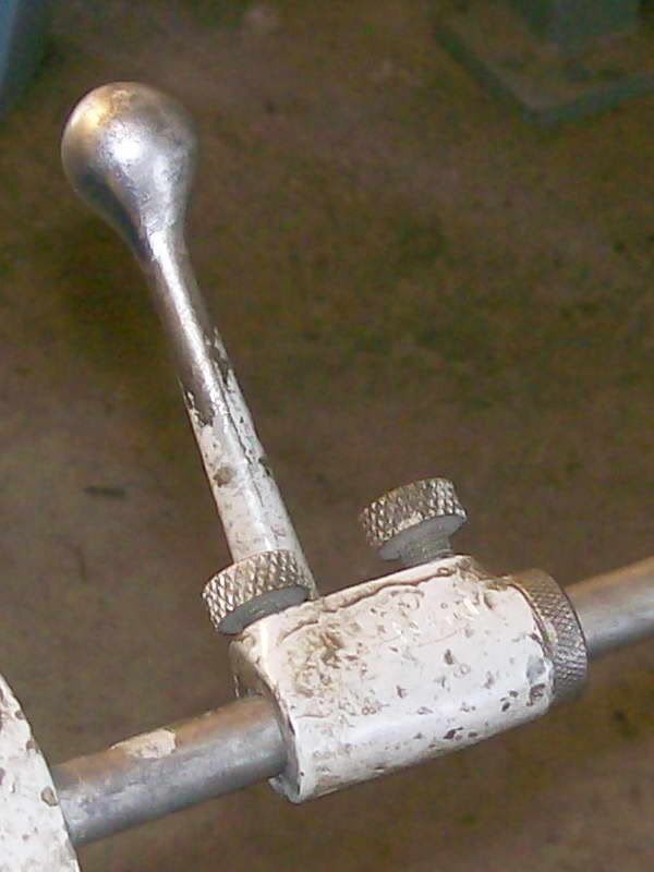
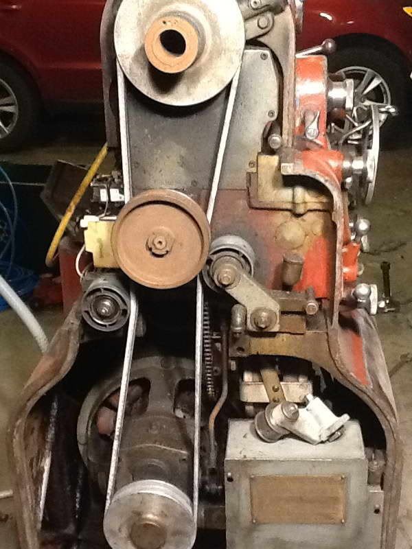
An interesting note on the ELSR: they normally have a movable handle/stop on the rod to the right of the apron to control the spindle direction. The movable stop on the left side is in place, but without the lever on the right it won’t stop when moving to the right. I hadn’t noticed the knob or button sticking out of the ELSR/feed direction casting (lower left corner) before; I’m not sure what it does. Another thing that I learned today is that ELSR was not an uncommon feature on a round-dial. However, looking at my archive I’m surprised how many are missing one or the other stop.
The machine probably didn’t have a collet closer from the factory. Machines that did had a two-piece cover on the top. It’s also interesting that the hand-wheel collet closer draw tube seems to be sitting in the holders on the rear. So, two different collet closers and no collet nose; no way to use either system without one!
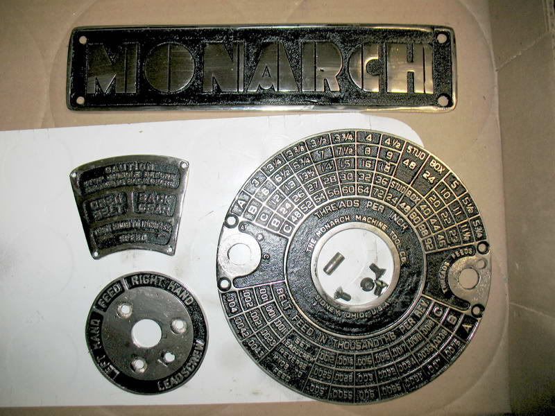
Reliable’s spec are pretty far off: Round-dials can’t cut 184 TPI threads. Round-dials could cut 50 thread pitches from 3 to 92 TPI. And feeds are 0.0010 to 0.0075”. The specs they quote are for a square dial. I’m also skeptical about the MT3 tailstock taper. Another error in the specs is the spindle speed: it has a 4000 RPM tach, so it’s probably set up for 4000 RPM, not 2500 RPM.
I can’t really tell from the photos, but the ways don’t appear to be pristine, however unless the machine was completely thrashed I would say that $2500 was a pretty good deal for this machine. Hopefully the new owner will check in here.
Cal
MONARCH 12.5" X 20" 10EE TOOL ROOM LATHE | eBay
It also has more options that I’ve seen before:
- Taper attachment
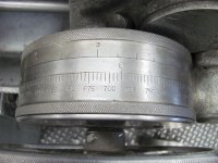
- Accumulating cross-feed dial
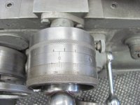
- Accumulating carriage feed dial!
- Electric Leadscrew Reverse (ELSR)
- Long cross-feed slide with dovetail
- Tailstock dauber (standard equipment, but most get lost over time)
I had forgotten that the accumulating cross-feed dial was even available on round-dials and I didn’t recall seeing an accumulating carriage feed dial “in the wild”. Neither option is listed in the 1944 round-dial brochure. Going back through my photos I did find 8 or 9 other round-dials with an accumulating cross-feed dials. I also found a photo of an accumulating carriage dial, but it was on a square dial.
An interesting note on the ELSR: they normally have a movable handle/stop on the rod to the right of the apron to control the spindle direction. The movable stop on the left side is in place, but without the lever on the right it won’t stop when moving to the right. I hadn’t noticed the knob or button sticking out of the ELSR/feed direction casting (lower left corner) before; I’m not sure what it does. Another thing that I learned today is that ELSR was not an uncommon feature on a round-dial. However, looking at my archive I’m surprised how many are missing one or the other stop.
The machine probably didn’t have a collet closer from the factory. Machines that did had a two-piece cover on the top. It’s also interesting that the hand-wheel collet closer draw tube seems to be sitting in the holders on the rear. So, two different collet closers and no collet nose; no way to use either system without one!
Reliable’s spec are pretty far off: Round-dials can’t cut 184 TPI threads. Round-dials could cut 50 thread pitches from 3 to 92 TPI. And feeds are 0.0010 to 0.0075”. The specs they quote are for a square dial. I’m also skeptical about the MT3 tailstock taper. Another error in the specs is the spindle speed: it has a 4000 RPM tach, so it’s probably set up for 4000 RPM, not 2500 RPM.
I can’t really tell from the photos, but the ways don’t appear to be pristine, however unless the machine was completely thrashed I would say that $2500 was a pretty good deal for this machine. Hopefully the new owner will check in here.
Cal


")


