What's new
What's new

CK TA Adjuster

beckley23

Titanium
Joined
Feb 19, 2003
Location
Louisville, KY, USA
A short time ago I started a thread about the CK's TA lens, and mentioned making a vernier adjuster similar to the EE's. I think I've come up with a plan for the adjuster, it's still in the thinking stage with a few rough sketches.
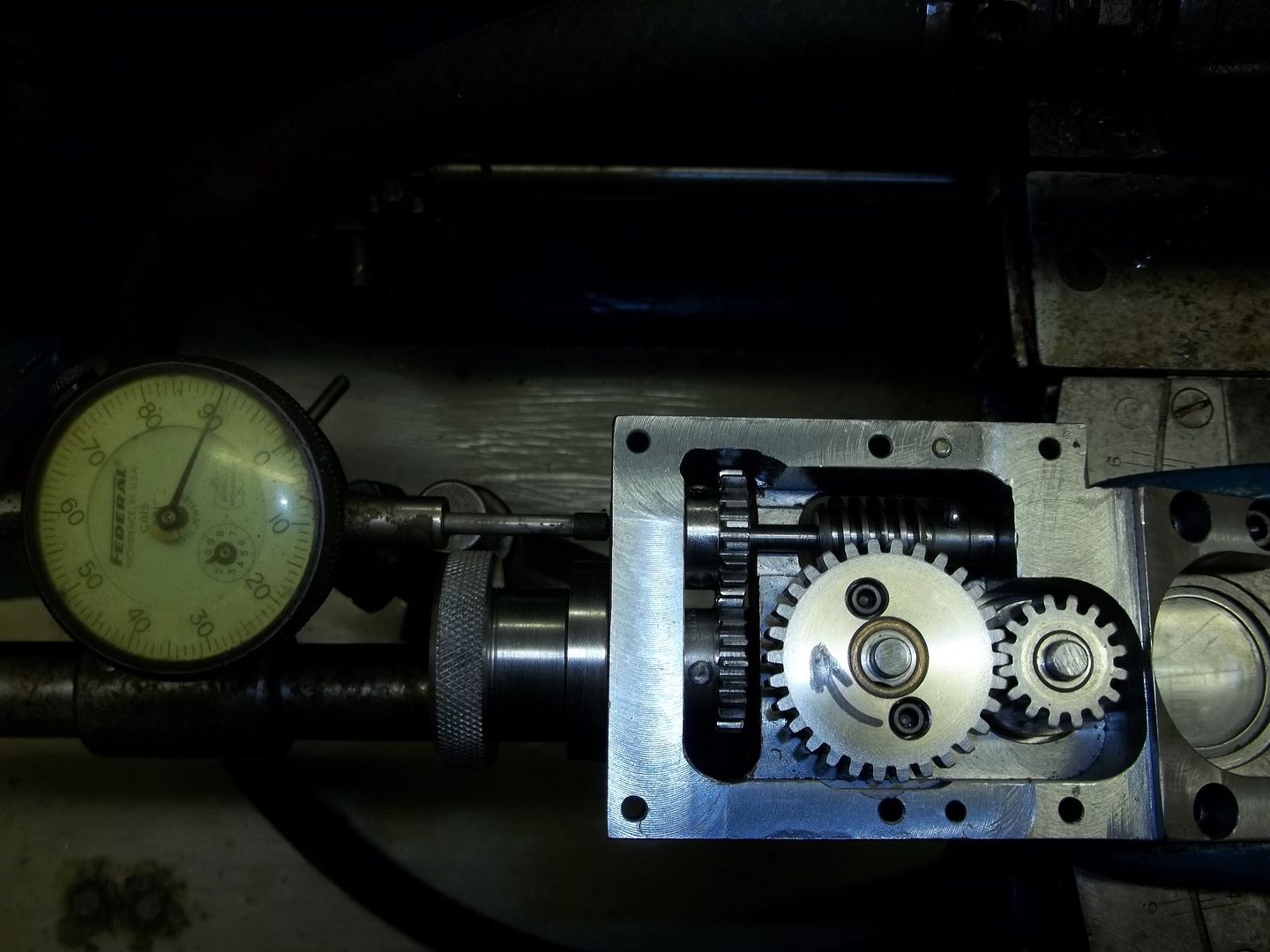
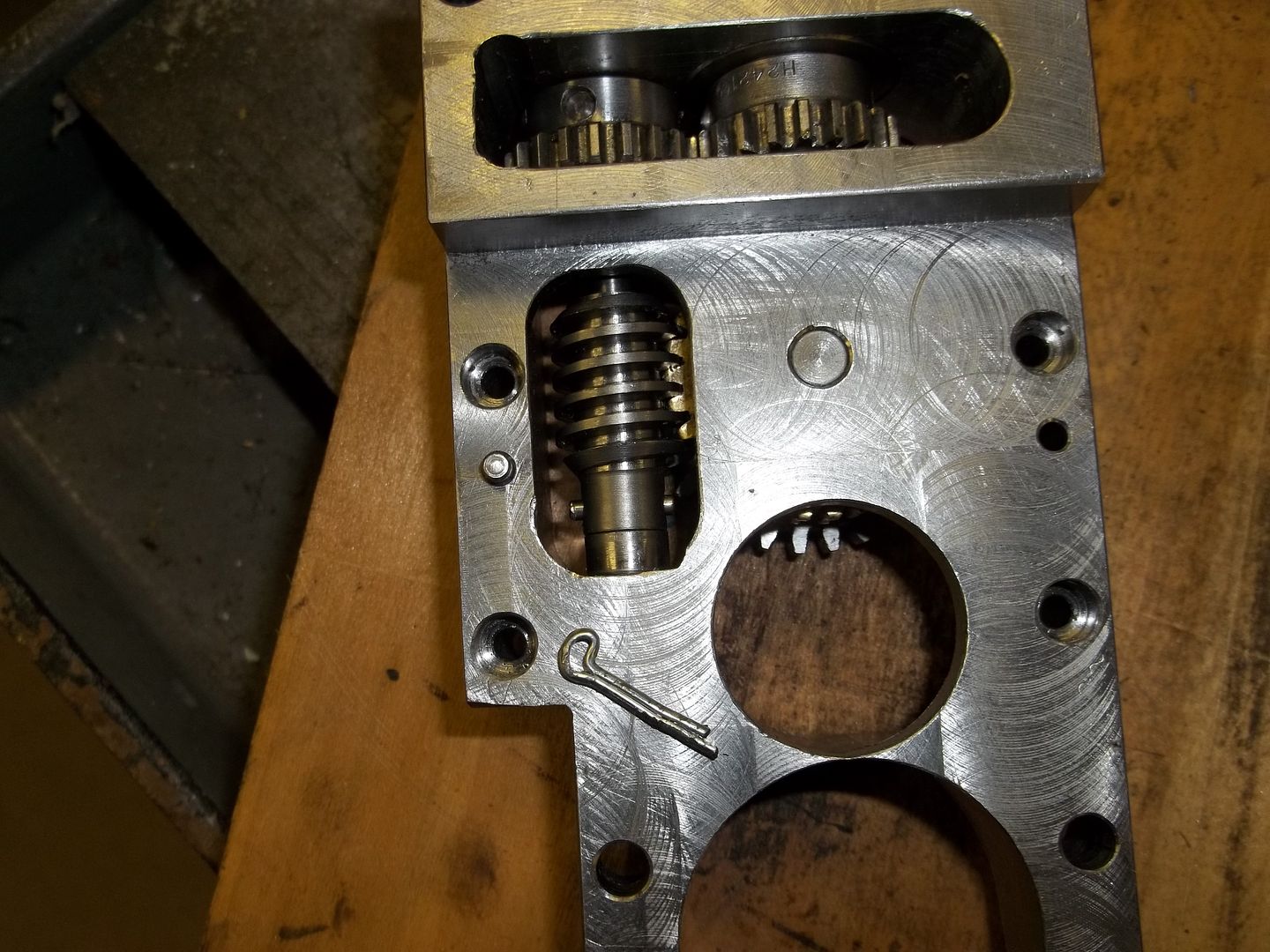
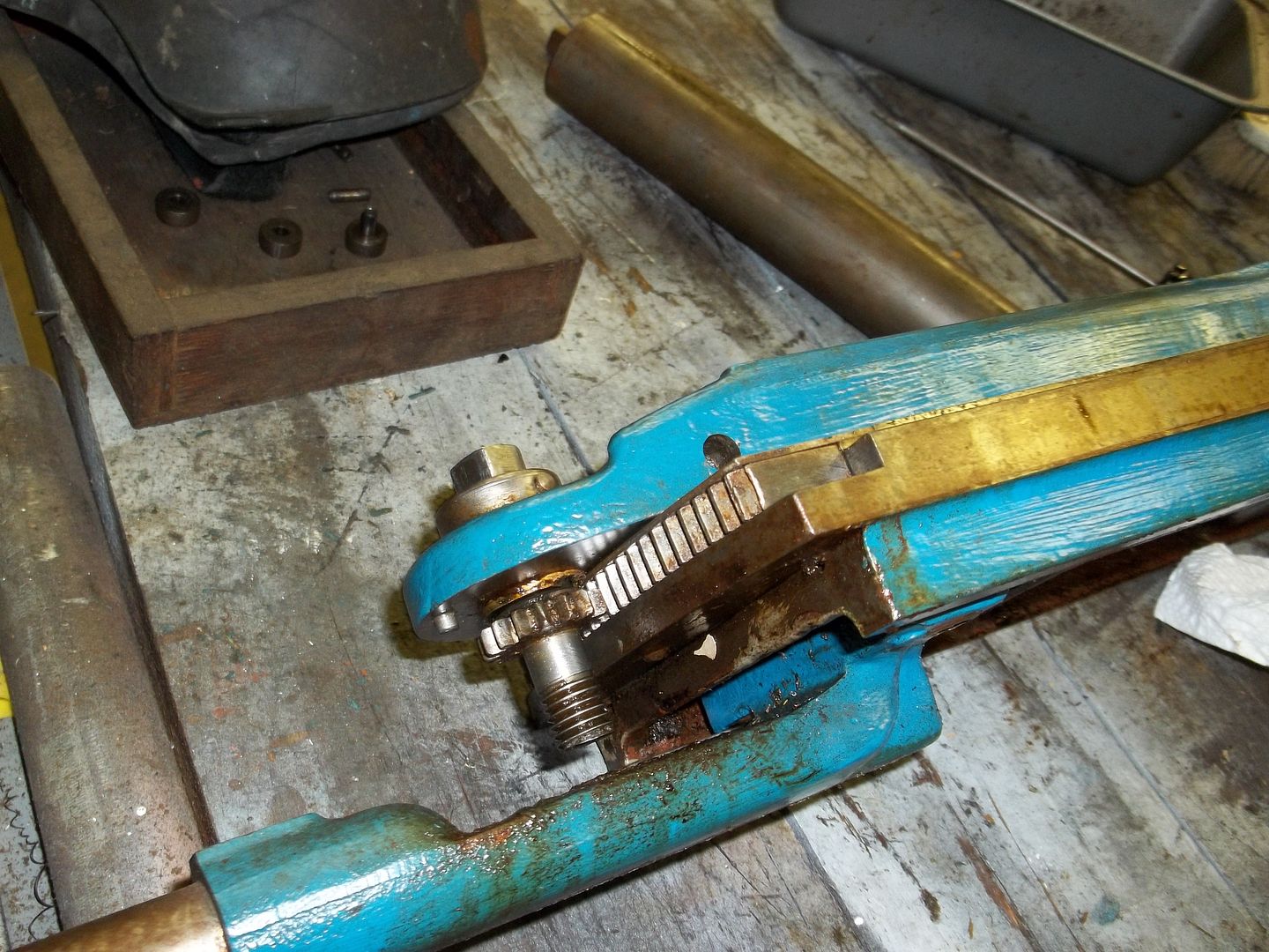
The EE's vernier adjuster is composed of 4 gears. There is a 30:1 worm and worm gear, a 36 T 32 DP compounded to the worm gear, a 36 T 32DP idler, and a gear segment of a 432 T 32 DP gear that is attached to the TA's swivel. This is all shown in the "Wreck Update" sticky. If you noticed the ratio of the compounded 36 T and 30T worm gear is 1.2:1, also the same ratio as the 432 T gear to the unmentioned 360* circle. In short, one revolution of the worm moves the swivel 1*. The vernier is calibrated in 60 divisions, for 1' adjustment capability. Expressed another way; every turn of the worm moves the 36 t gear 1.2 teeth, every degree is 1.2 teeth on the 432 gear segment.
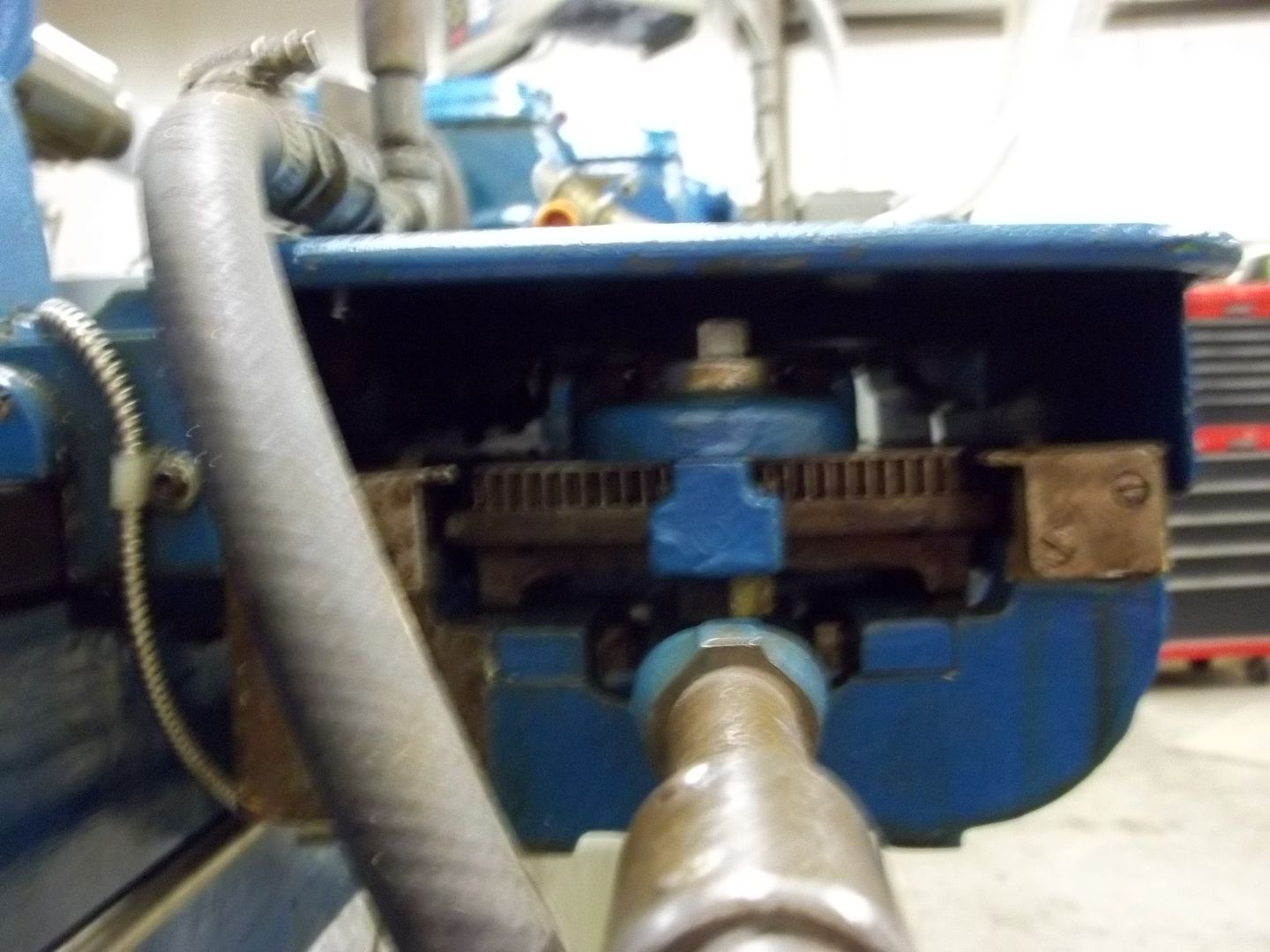
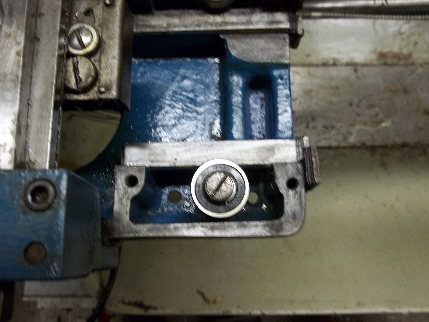
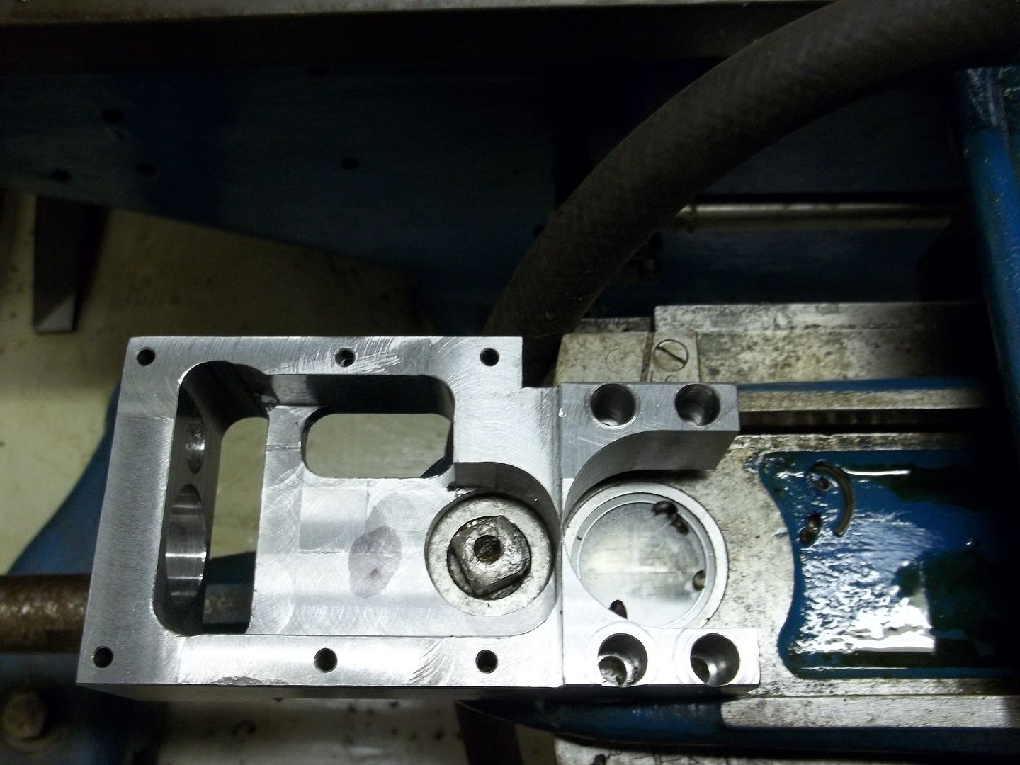
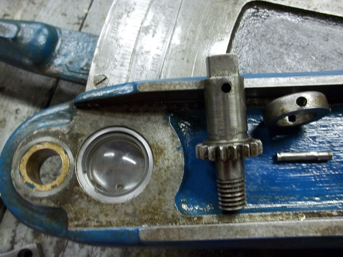
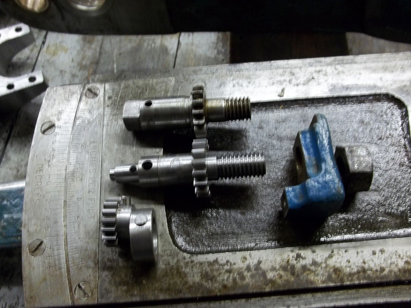
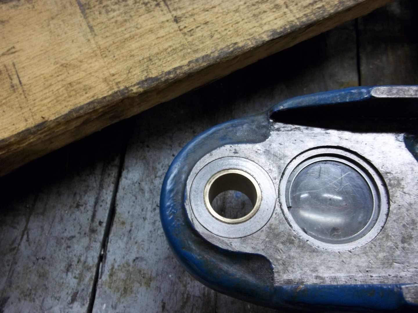
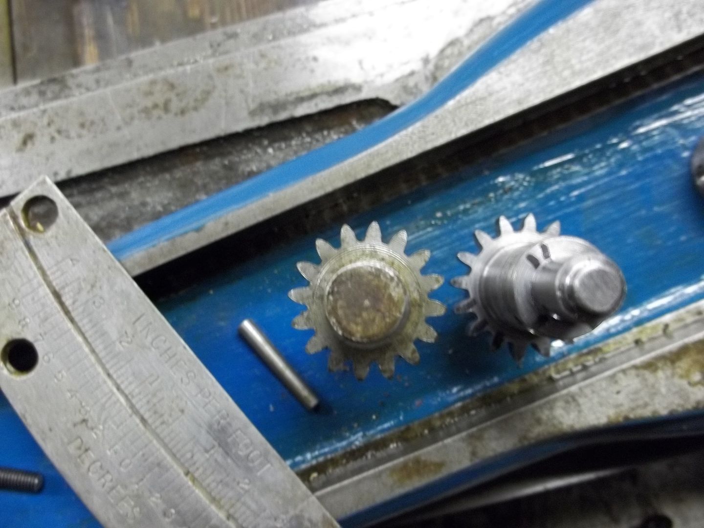
The CK is much different from the EE, especially in the adjusting details of the TA, which can be very time consuming. Adjusting the EE in 1' increments is relatively easy, with the vernier adjuster, not so on the CK. All the CK has is a 16T gear pinned to the adjuster shaft, which also serves as the clamping bolt. If you're watching the lens, you can't see the movement, it is strickly a guessing game, even using a DRO as your guide. Sometimes you get lucky, I made the "Wreck's" new tailstock spindle on the CK, and didn't have to use a reamer.
100_0343.jpg


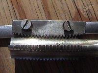
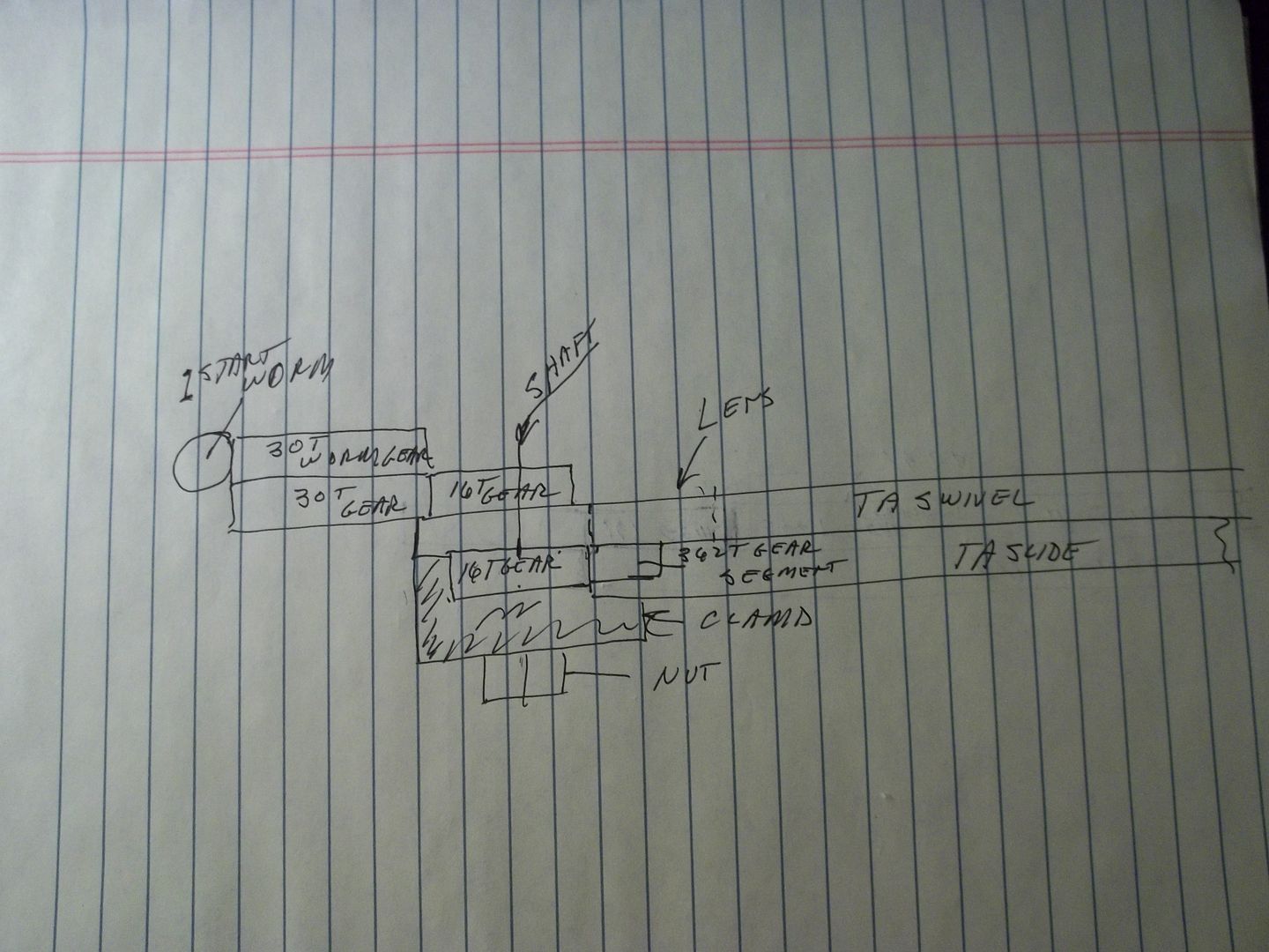
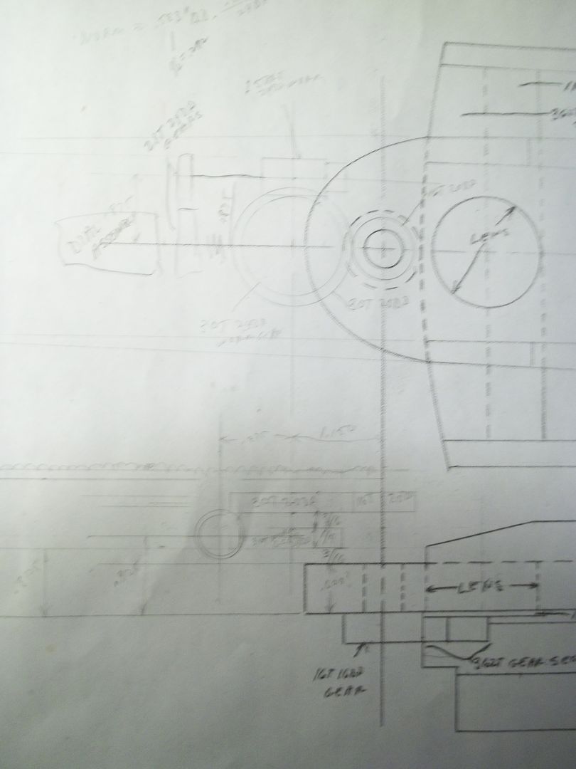
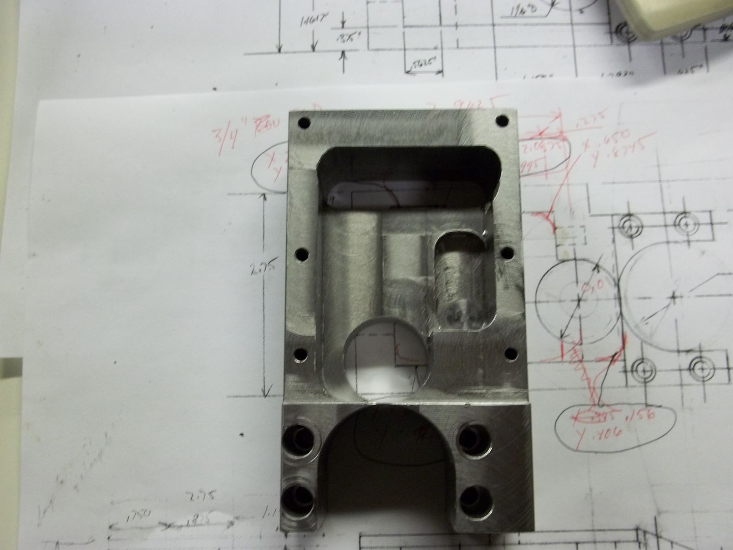
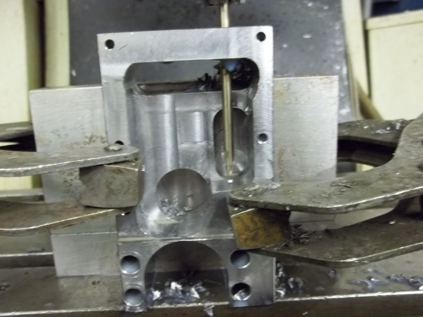
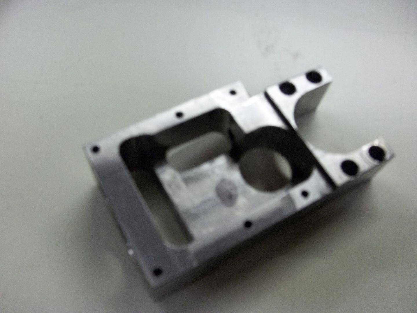
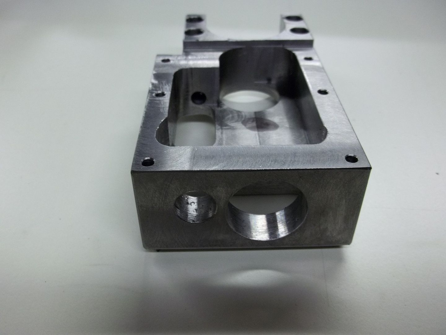
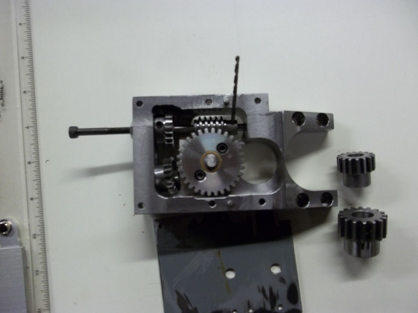
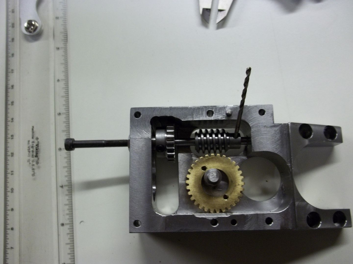
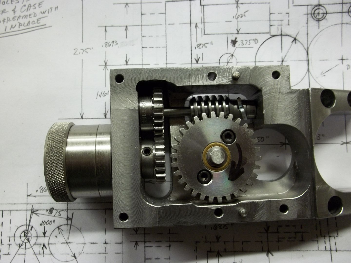
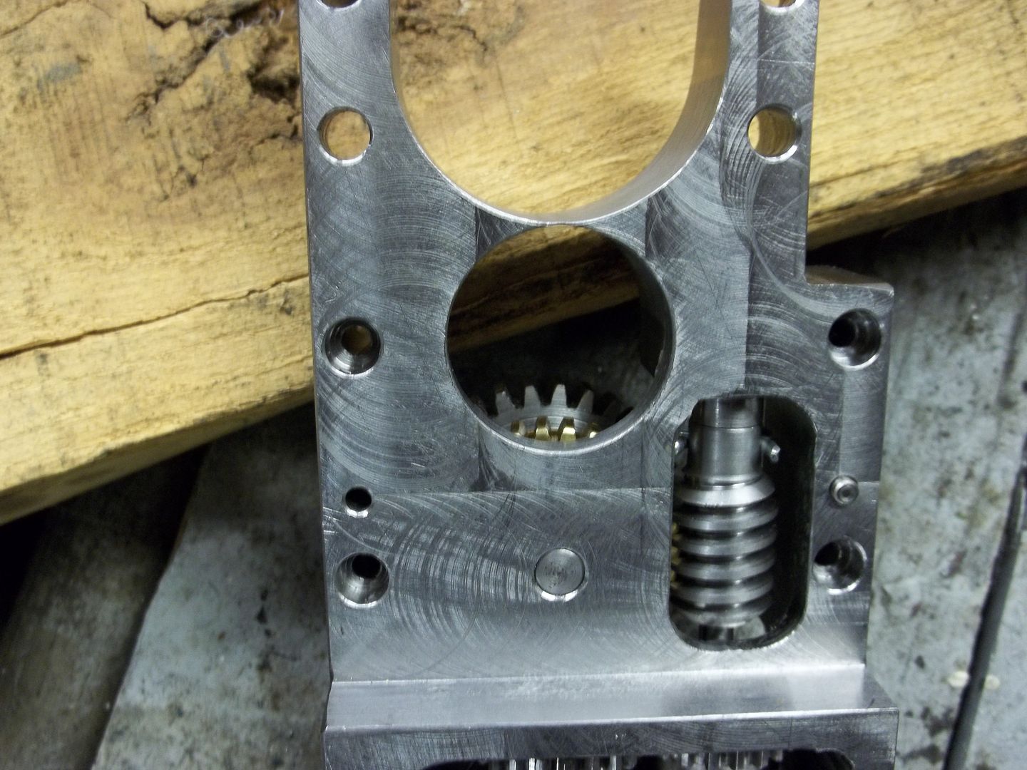
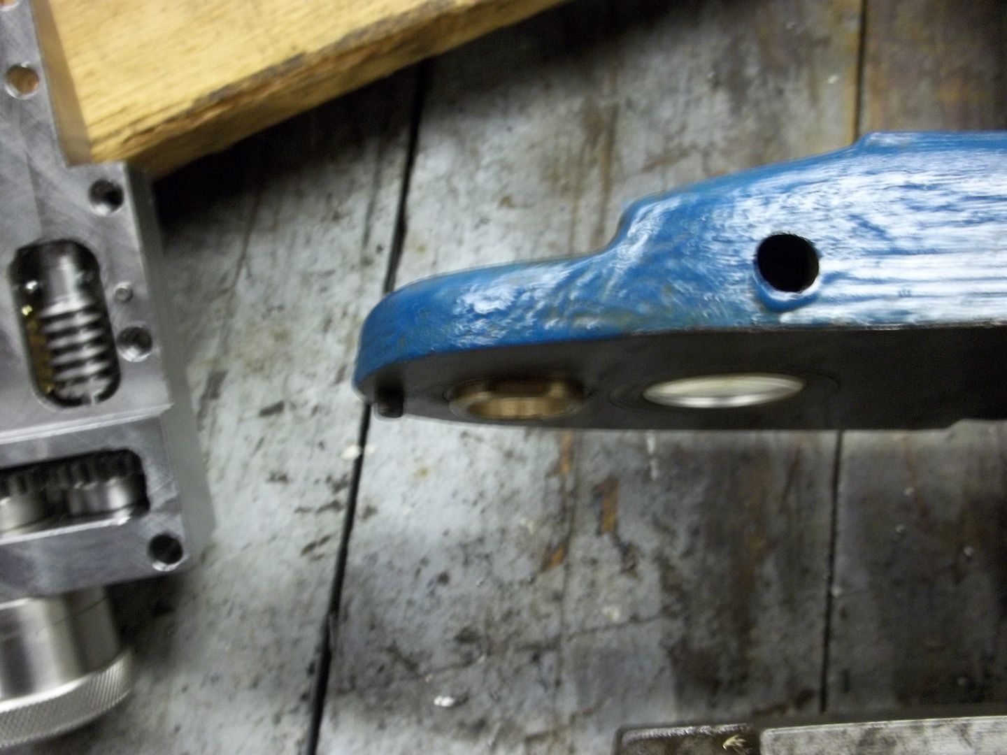
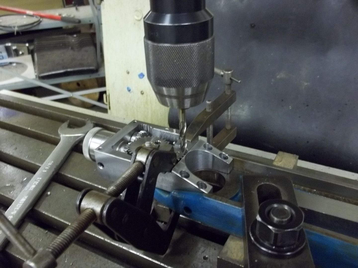
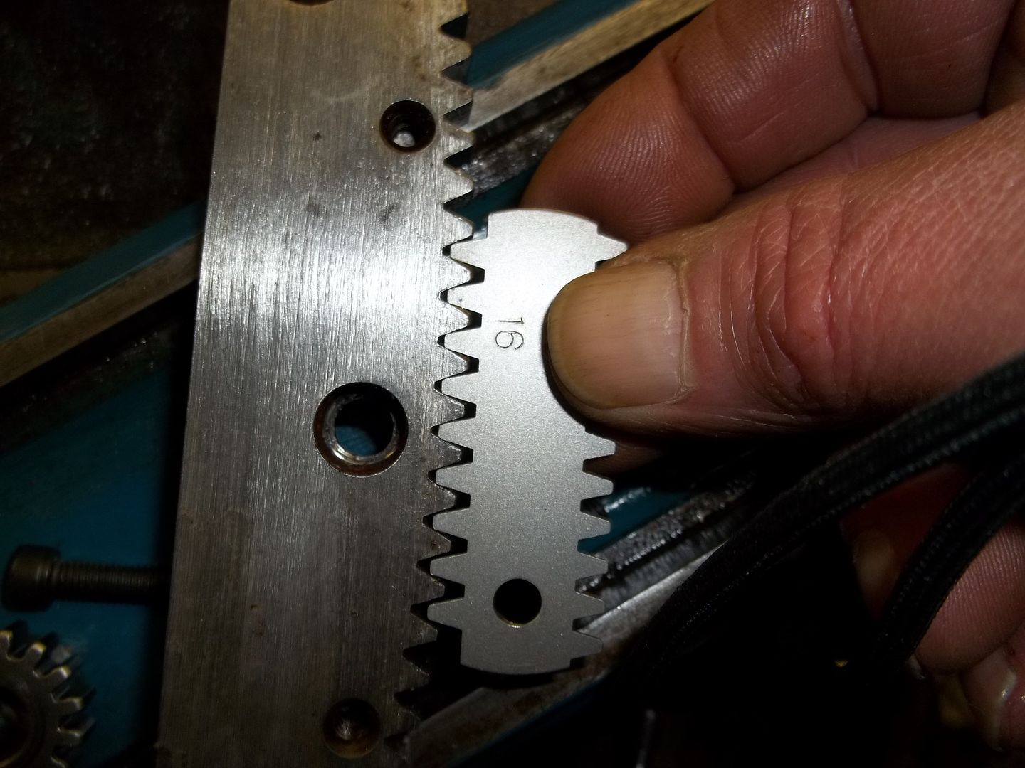
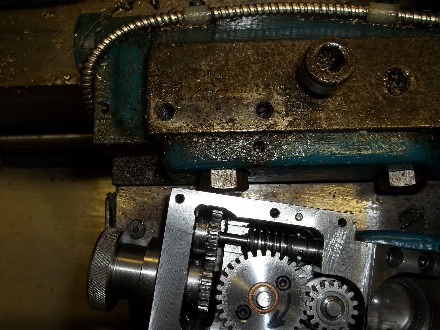
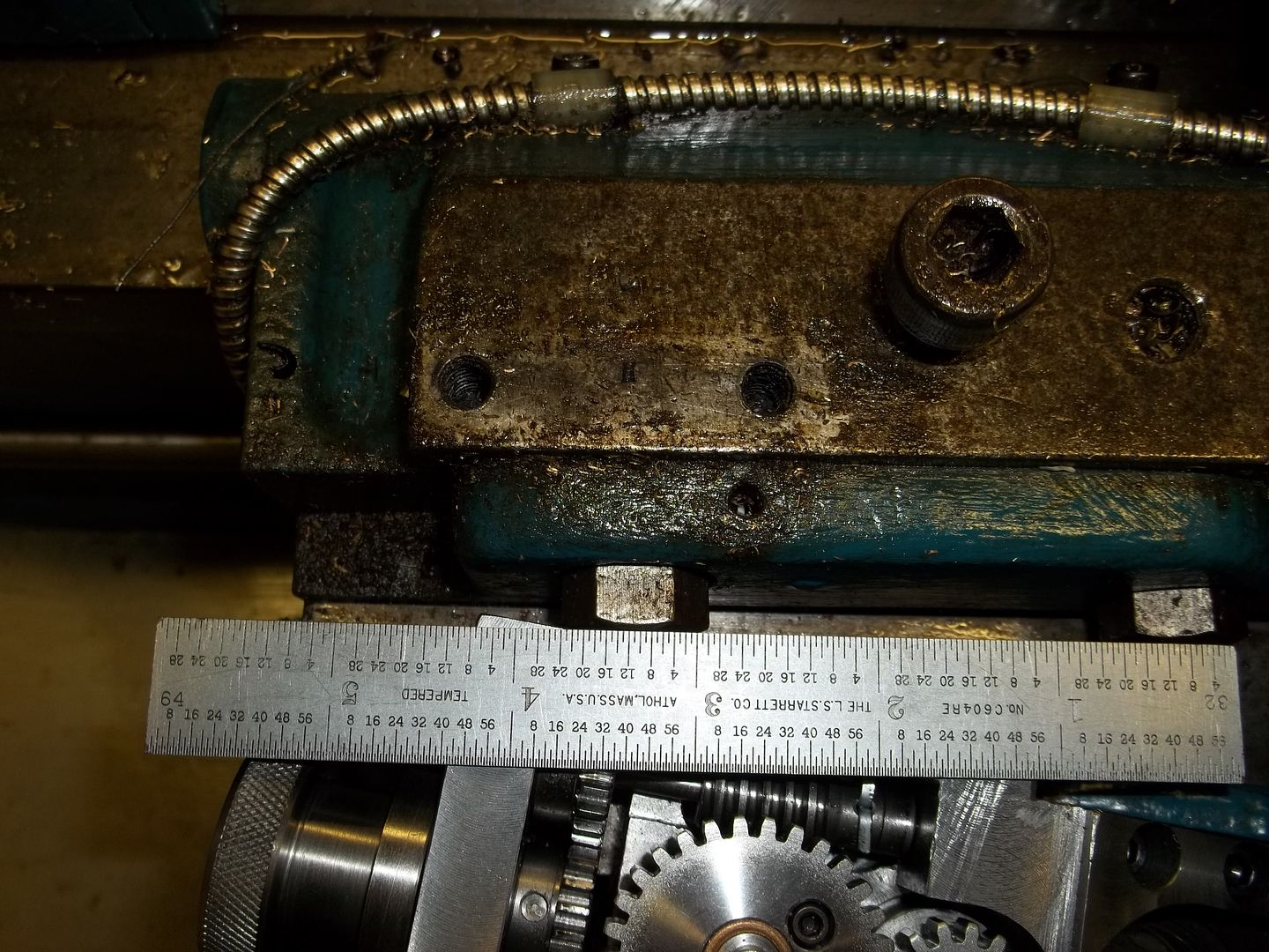
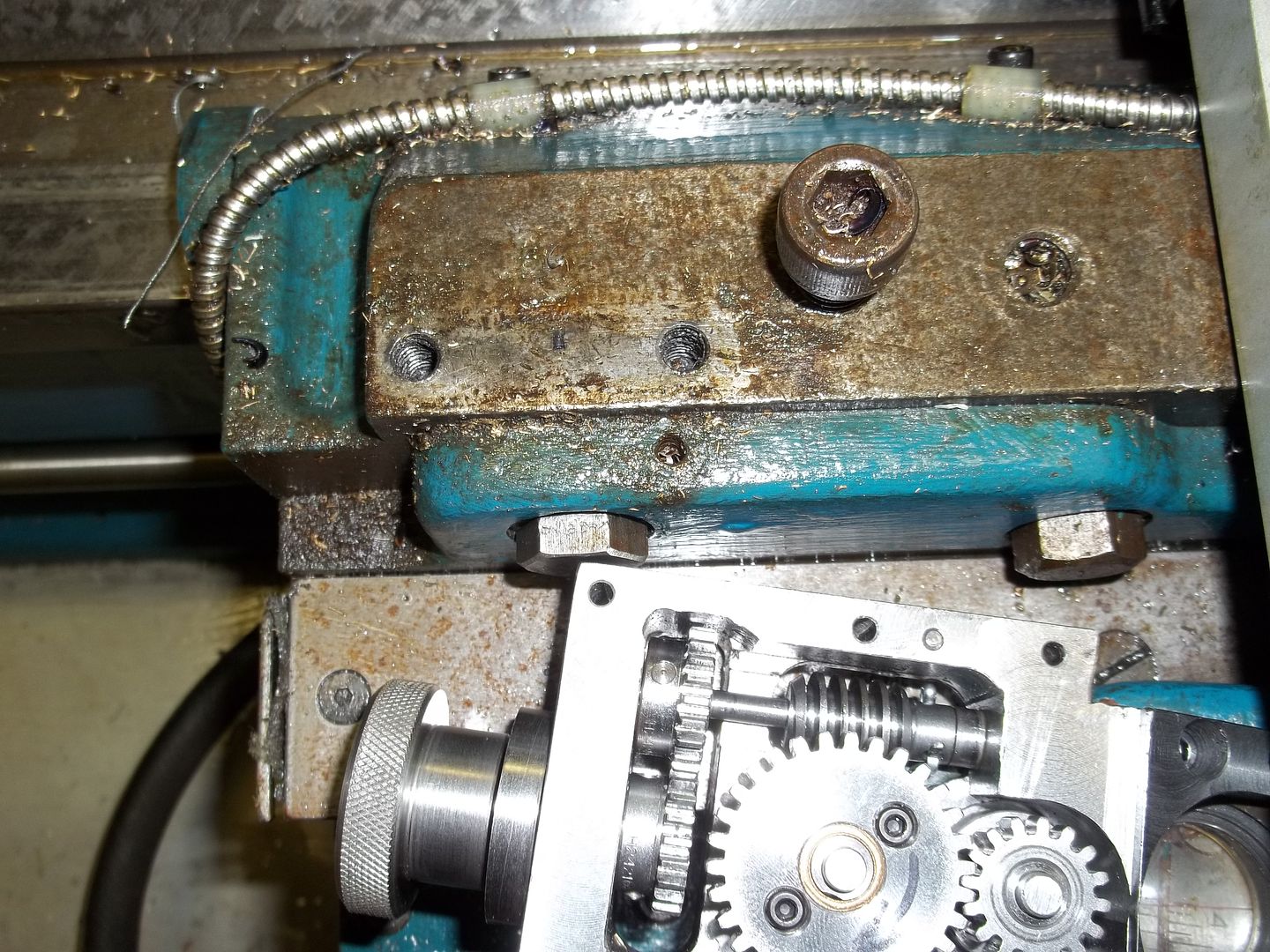
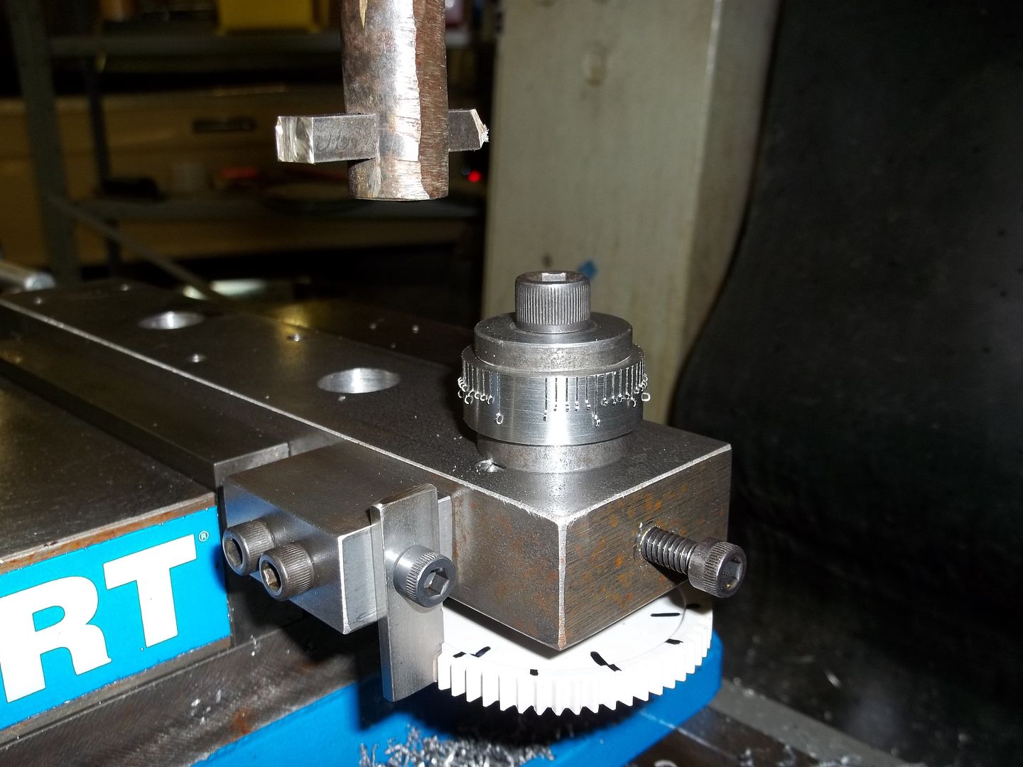
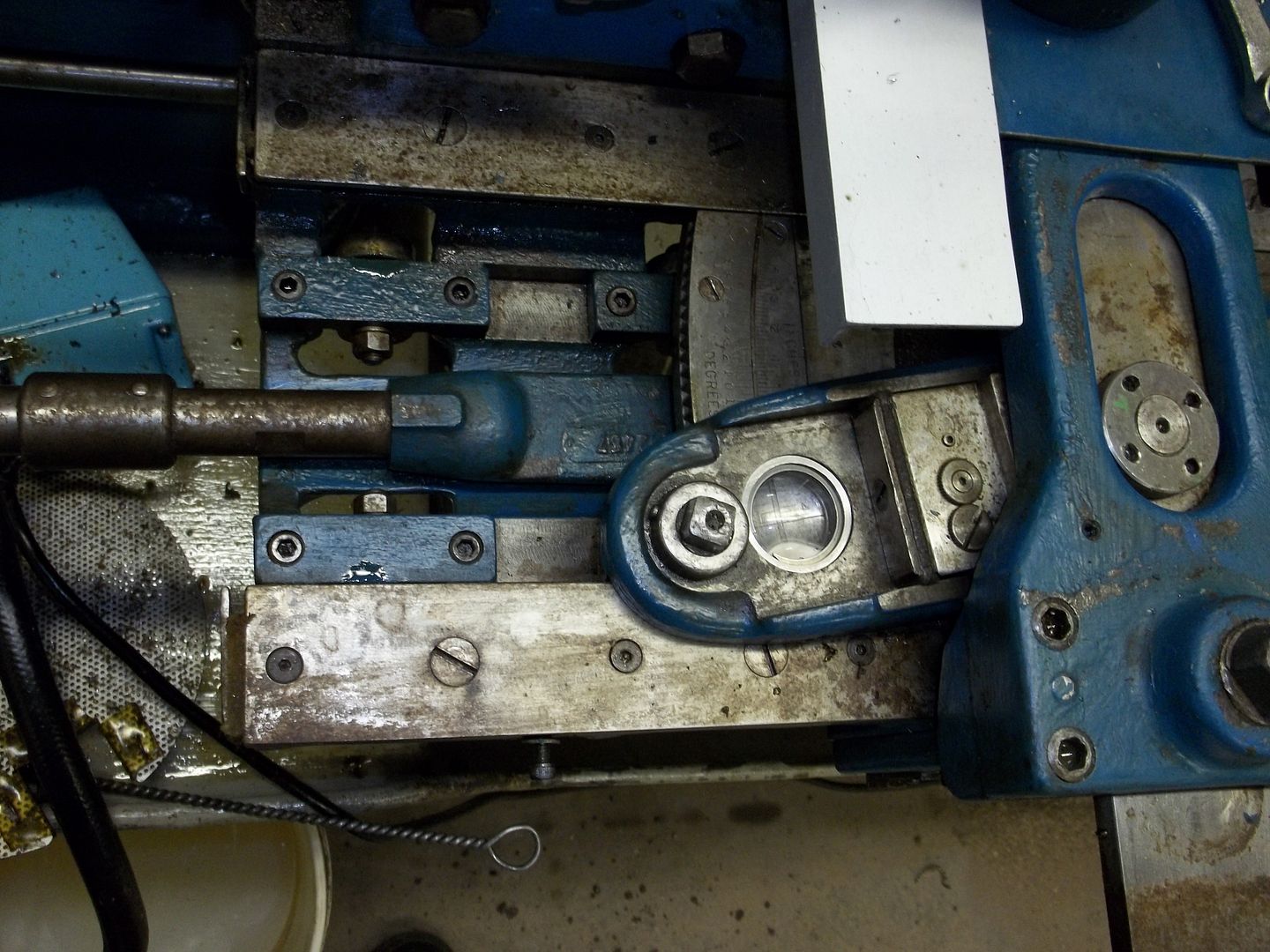
The gear segment is part of a 362 T 16 DP gear, each tooth is .994475*, attached to the slide. It is adjusted by the 16 T 16 DP gear, which has a 1/2" square drive on the top side. If I've done my math, correctly, if I use 30:1 worm gear set driving the 16 T gear, each revolution of the worm should move the swivel approx 1/2*. The teeth on the worm are 12* apart, and the teeth on the 16T gear are 22.5* apart. Close enough for horseshoes, I just need references for adjustments. Anyway, this is about as far I've gotten, now to figure out how to get this all in there, that's going to be the trick. It's hard to tell from the picture, but there's not much room in there especially after the cover goes on.
100_0346.jpg

Harry
 
Last edited by a moderator:
Hi Harry,

Please forgive, in advance, my ignorance of the finer points of gear design.

This is a very interesting problem and I appreicate you looping us in on your design musings.

How did you determine that the gear segment segment it 362T? Could it be 360? Correct me if I'm wrong, but isn't the difference in pitch diameter .125"? If so, it would be odd that they wouldn't use a 360T gear...

Could you make a custom 360T segment and mating gear that would work, similar to what you did with the wreck (I think) on the cross-feed screw spline gear?

In the first picture, is there a nut or clamp that goes on the threaded portion of the adjuster shaft? If so, how do you tighten it?

I know that worm wheels have a different profile than a spur gear, but could you make a screw that could directly drive the segment? One revolution of the screw would give you about a degree of adjustment. Since it doesn't need to provide much force and you could live with the backlash, I would think that the mesh could be pretty sloppy and work.

Attached is a photo of a standard tap meshed with the adjuster segment from my 10EE. IIRC, it's 3/4-16 tap.

Cal
 

Attachments

  • DSC00004.jpg
    DSC00004.jpg
    46.7 KB · Views: 322
After getting the cobwebs out of my head, it occurred to me that the gear train for the adjuster was staring me in the face after looking at the EE's gear train again. Basically just copy it, substuting a 30 T gear in place of the 36 T that is compounded to the 30T worm. 1 revolution of the worm rotates the worm gear 1 tooth, and the same for the 30 T spur gear. The 16 T spur gear(s) are now idlers, and don't count in the ratio, thus the gear segment is moved 1 tooth.1 tooth of the 362 tooth gear segment is close enough to 1*, actually .994475*, that I'm not going to be to concerned about an "exact" 1 minute increment. All I'm after is controllable calibrated movement of the swivel. You don't quite get the control with a wrench on the square end of the shaft as it's presently set up. I checked the control out on the EE the other day, and it seems to work a lot better than trying to minutely move a wrench.
Below is a sketch of the proposed gear train. I'll leave the existing 16 DP gears as is, since I can't change them, but the worm gear train will probably be 24 DP. One other change is that the worm will be parallel to the swivel's travel and not 90*, as it is on the EE. Now, I have to get some dimensions to see if this is at all possible.

100_0351.jpg


The 362 T gear was determined by measuring the center distance from the center of the swivel to the center if the 16T gear. That number is 11.8125", subtract .500" for the pitch radius of the 16 T gear to get the pitch radius for the segment, multiply by 2 for the PD and then multiply by the DP, which is 16, for the number of teeth. I checked that several times, because 360 is a lot easier to work with.
Harry
 
...
The 362 T gear was determined by measuring the center distance from the center of the swivel to the center if the 16T gear. That number is 11.8125", subtract .500" for the pitch radius of the 16 T gear to get the pitch radius for the segment, multiply by 2 for the PD and then multiply by the DP, which is 16, for the number of teeth. I checked that several times, because 360 is a lot easier to work with.
Harry
Thanks Harry.

I see how the clamp limits what you can do. I take it the dowel pin visible in the first photo is for the top of the clamp.

It's too bad that they didn't use a segment of a worm wheel, directly driven by a suitable worm.

Cal
 
Started the design process, which is getting a bit complicated than I envisioned. Went from 5 gears to 7, including a 16T 16DP gear to mesh with the 362T gear segment. I can see quite a bit of backlash. One minor change from the rough sketch above, is the inversion of the 30T gears. The gearbox is proving to be a challenge, but I'm getting there. The problem is getting all this stuff squeezed into a small space, without compromising the range of the TA.
The first picture is of the drawing for the gear layout, fortunately I've got 2 more copies of the dark lined section once I get things totally figured out. Sorry but you're going to have to strain your eyes.
100_0353.jpg


Here is an shot of where above has to go. From the top of the slide to the bottom of the cover is approx 1-5/8". That's the easy part, the dimension that's causing all the trouble is the 1.041", let's call it 1.025" for safety, from the bottom of the slot in the slide to the bottom of the cover.
100_0352.jpg


On another issue that Peter discussed several years ago concerning coolant damage to the EE's TA bearings in the bracket, I finally figured out what he was talking about, when I cleaned that mess up several weeks ago. 2 holes got drilled in each of the pockets.
100_0350.jpg

Harry
 
Finished up the gearbox design, at least as far as I'm going to go. Started out with a block 2" X 3-1/4" X 5-3/8" and whittled it down to 1-7/16 X 2-3/4 X 4.880. Started the pictures about half way through. The first one is of the block grossly sized, with the internal cavity cut out.
100_0355_zpsa4da3e15.jpg


I knew this center drill would come in handy. Drilling the center start for the internal worm shaft bushing.
100_0358_zps6b7cffe4.jpg


The next 3 are the side, top, and end views. The big hole on the end view isfor the dial assembly. It is offset from the main center line .0055" and .100 below the smaller hole on the left, which should give me the .875" center distance for the 21T 24DP gears.
100_0360_zps4cb1f921.jpg


100_0359_zps049f7017.jpg


100_0361_zpsb8a54b58.jpg


Making sure it's going to go where it's supposed to go.
100_0363_zpsb740f809.jpg


The gearbox is not completed, I need to get the cover made first, so that the shaft holes can be drilled and reamed for the compounded 30T gears.
Harry
 
Well, I'm slowly making progress. This has been an adventure, that I would definitely rethink in any future iterations of this device. All machines have at least one bad area. In Monarch's case it is the design of the TA's adjustment, especially in the C and 60/61 Series, that is lacking. The EE's TA adjust is very nice, and this adjuster is very closely designed to those features, that I'm sure you've noticed.

The work that still to be done is; engraving the dial, making a couple screws, and the 16T compound gear and clamping shaft, and of course mounting the assembly to the swivel.

Checking the fits. The screw on the left is for assmbly purposes, only. The small gear on the right meshes with the 30T center gear, and is compounded to the large spur gear that meshes with the 362 T gear segment.
100_0364_zpsfd79d597.jpg


I'm sure you've noticed that I've had some clearance issues, 3 were anticipated and 1 was'nt. The three interior corners, 2 have been crudely corrected and the third will be corrected. There is thrust spacer that goes between right end of the worm and the case, and the corner needs to cleared out a little. The "unexpected " issue is the relief cut into the interior bottom edge for the 30 T gear.
100_0365_zps453dc9f8.jpg


The worm shaft spacer has been made and installed, and yes, that is a cotter pin in the worm. Originally, I intended to roll pin the worm to the shaft, but when the roll pin went flying, I decided a different approach was needed. The arrow is the rotation when the adjustment knob is rotated CW when looking at the ************************. Personnally, this is the desired rotation, as the swivel moves away from the front of the lathe.
100_0367_zpsc115998f.jpg


The dial is on the right, the knob on the left, and the key is top center. The bronze spacer projects about .002" out of the knob to allow free spinning of the dial.
100_0368_zpscfd8fd68.jpg


The adjuster assembly assembled. Othe than the shaft, gear, spacer and key, the other 3 pieces are SS.
100_0369_zpsd48df60f.jpg

Harry
 
Design Issue

I'm in the process of designing the ajusting gears and clamp shaft, and have run into a question(s). In the picture below, this is the first time I've removed the gear and shaft from the original, the bronze bushing in the swivel is 11/16 ID X 15/16 OD. The clamp collar is attached to the shaft by taper pin and is 1-1/8 OD. The bearing area is the clean ring around the left most hole in the swivel, and it has been adequate. With the new adjuster the hole in the case is 1-1/16 ID, which will reduce the amount of bearing area. I'm a little concerned about the amount of bearing area, and I'm considering the removal of the bronze bushing and putting in a counterbore approx 1/4" deep and then installing a flanged steel bushing with a bronze liner that will allow for a larger bearing area to clamp against.. I get a bit heavy handed when tightening the clamp nut.
The question I have, is the clamping area as it is, enough, or should I go for more?
100_0371_zps3208c3eb.jpg

Harry
 
My post on 3-16 turned out to be unnecessary, as I found out yesterday when I tried to fit the clamping collar in the hole. Turned out that collar had to be reduced in diameter from 1-1/16 to .950" to clear the worm gear, there 's a picture below, illustrating the problem. The flanged bushing became mandatory in order to provide bearing area for the collar. The swivel was set-up on the mill and a 1-3/16"D X 3/16" deep counterbore was bored, the bushing with a 3/4" hole was made and pressed in, along with a flanged bronze bushing with a 5/8" bore pressed in from the bottom, pictures below.

The compound gear shaft was designed on the proverbial napkin. Next time I'll use the drawing board, as I was contending with several other issues not readily apparent until you get into it. One issue that I had, was deciding on how to attach the gears and collar to the shaft. The choices readily available to me were roll pins, dowel pins, or taper pins. In the end I decided on taper pins. I feel that they are easier to get out, if you know where the small end is, than the other two. The 16T 24DP gear and the collar have to be removed and installed with the shaft mounted to the swivel. This is the same way Monarch did it. You will also notice in the pictures, that the new clamping collar is thicker than the original. That is because the taper pin used in the original came out bent(you may be able discern that in one of the earlier pictures), and I felt that a bigger taper pin would go long way to solving that problem, thus the thicker collar.

This project is just about done. The adjuster will get mounted to the swivel next. I still have the 2 screws and the dial to complete.

100_0372_zps2c83a220.jpg


100_0375_zpse56ca793.jpg


100_0376_zpsa2628a41.jpg


100_0377_zpsea3a1318.jpg

Harry
 
The method of locating the screw holes in the swivel is rather crude, but effective. Used a drill bit to center the spindle in one hole, and the DRO to locate the rest. The just drill and tap the mounting holes.The clearance holes for the 10-32 in the case are 7/32, so there's a bit of room for adjustment. The biggest problem I ran into is the gear tooth form of the gear segment and the 16T pinion, definitely not involute, which goes a long way to explaining why involute and this form wouldn't mesh. The new 16T 16DP gear had to be modified. A bit of grinding, sanding and filing did the trick, its not perfect but the gears do mesh, although the backlash seems to suffered. The other issue was the amount of backlash in the worm shaft. The cause was traced to the cotter pin, which got replaced with a "dowel" pin that I cut from watchmakers wire stock that been hanging around from the 70's. The rest of the pictures are checking the clearances for the movement of the swivel, especially next to the TA's bracket mounting screws. The solution was to either clip the edge of the gear case, or reduce the screw head thickness; chose the easy option. The others show the amount of clearance with the chip cover in place. The blue chips on the cover are from the rolled edge of chip cover.
100_0378_zps9d62da7c.jpg


100_0379_zpsc04d6e1f.jpg


100_0380_zps9e8678a2.jpg


100_0381_zpsf1e7d7d4.jpg


100_0382_zps65695019.jpg


100_0383_zpsb820ec3d.jpg


100_0384_zps1479b9a5.jpg


100_0385_zps1211e2ba.jpg


Cont. next post
Harry
 
Did some checks on the movement of the swivel, and found a "big" problem. It was easy going in one direction, but the other direction was extremely difficult. After messing with the adjuster, and trying several remedies, including machining both faces of the compound gear for hardened thrust washers, approx .0045" thick, selectively loosening the mounting screws, I finally checked the corners of the base where it is within the swivel. Even though they had the edges broke, it wasn't enough. A couple minutes at the belt sander took care of the problem. While all this was going on, I also checked the clearance for the dial thumb screw; there wasn't any, and this had to re-thought. Considered spring washers, but decided that was going to be very difficult at this stage, then I remembered how Monarch did the TS micrometer dial, and went had a look at mine. Monarch used a 3/16 spring and ball, except that I needed them smaller due to the wall thickness, 3/16", of the dial. 1/8" was the next choice, and that was the direction I went. I drilled 2 1/8" holes, 180* apart in the dial .450" deep, just in case the springs weren't strong enough. The end result was that one spring was more than enough, but off centered the load enough that there was a rough, gritty adjusting action, two springs proved to be the solution, but they had to be shortened approx 3-1/2 coils each, and I may shortened them a bit more, the adjusting action seems to be a bit tight.
Another issue was that with the springs in place, there was no thumb screw that I could use to do the adjustments, as there is on the EE's adjuster dial, and adjusting using a relatively smooth surface to grab on to with oily fingers wasn't appealing, the dial needed to have knurled surface. No room on the first dial so I made another dial 1/8" longer that has knurled surface.
One other issue that I wrestled with since the beginning was indexing the dial for the divisions. I no longer have a dividing head, which was how I did this in tha past. I used the time honored method that I think everyone will recognize. The long sharpie lines are the 10' marks, 3/8" long, the short sharpies are 5' marks, 5/16" long and all the rest are 1/4" long.
The base got its first coat of paint today, and this project should be ready for testing sometime next week.

Engraving the dial, the first time. The rest need no comment.
100_0398_zps0a91dc2f.jpg


100_0399_zps034d752a.jpg


100_0400_zps657288dc.jpg

Harry
 
It Works

Today I tested the adjuster by setting up a couple of tapers, a #2 MT, and a NST milling machine taper. I was expecting the backlash in the gear train to give problems, but that wasn't the case. I found the angle need, and then set the taper a bit less, and then used the adjuster to bring it in reading on the DRO's Y and Z axii. The set-ups went a lot faster than I anticipated. No more tapping on the wrench, hoping that the little tweek needed was gotten. I'm going to have to find a new way to invent words.

The set-up shown is for the NST taper.

100_0401_zps98c62e43.jpg

Harry


Back
Top