The CI gib discussion was good and timely for me since there is a similar gib on the Rivett 608 I am restoring. I am definitely no pro at this, but it will be the 4th machine I have scraped-in, so I have some credit hours in the school of hard knocks.
I noted the side discussion about the Schaublin bed, which is typical of jeweler's lathes, and some Rivett machines.
The Schaublin comments were, however, not encouraging..... The 608 has the same situation of bed cross-section, on the carriage where the slide rest fits. I will eventually need to probably align the crosslide by working on that interface, unless I find I can scrape the seating surfaces of the "carriage angle" part and align that way.
And, the bed also has a similar situation...
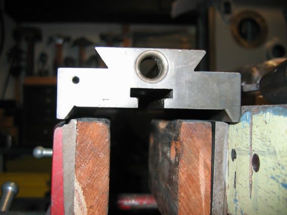
I already have the slide rest assembly done, other than final fitting the bottom of the crosslide to the carriage. They lock together and the actual slide is the top surface of the part that fits on the carriage. You can see the slide dovetail, and the three under- surfaces that fit to the top of the carriage angle.
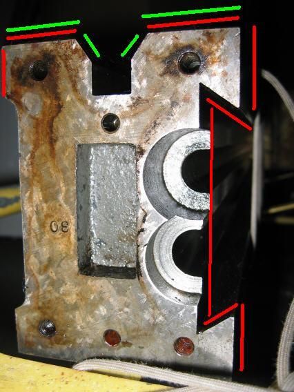
The green lines in the picture below show the surfaces that the headstock and tailstock contact. I will have to work on them, because the bed needs scraped, due to wear.
The red lines are even more interesting, because they show the surfaces that the carriage contacts. Apparently it contacts ALL of these simultaneously, although the top of the bed is contacted by the separate "carriage angle", which allows some scraping of flat surfaces between it and the carriage to align it. The gib is at the top of the dovetail.
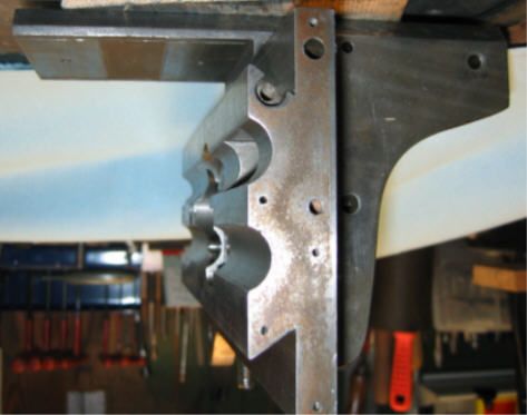
The carriage angle is a part that fits on the actual carriage.... here it is shown in approximately correct position on the carriage. the generally flat part is the "carriage" and the angle is the rounded part that fits against the carriage and sticks out to the left. If the picture looks odd, it is actuually upsy down so as to show the parts as they fit on the bed.... I set them together upside down to get the photo.
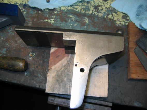
Here's the carriage angle by itself. You can see the surfaces that bolt up to the carriage.
I haven't figured out exactly where to start on this, and felt like a dummy... but now I don't feel quite so bad about it..... But I still don't know where to start.
My inclination was to start on the top surface, and get the headstock and tailstock alined, then make the rest fit.
The "make the rest fit" would presumably be to first get the dovetail area set up straight and aligned with the top, then get the carriage scraped to fit it.
Last bit to get the "carriage angle" to fit the bed, possibly with Turcite to fill in the gap I expect to find after scraping.
Maybe also Turcite to raise the carriage up to align with the feed rod and lead screw. Clearly they are not moving relative to the bed..... and I expect the carriage to shift down too much to ignore.
I noted the side discussion about the Schaublin bed, which is typical of jeweler's lathes, and some Rivett machines.
The Schaublin comments were, however, not encouraging..... The 608 has the same situation of bed cross-section, on the carriage where the slide rest fits. I will eventually need to probably align the crosslide by working on that interface, unless I find I can scrape the seating surfaces of the "carriage angle" part and align that way.
And, the bed also has a similar situation...
I already have the slide rest assembly done, other than final fitting the bottom of the crosslide to the carriage. They lock together and the actual slide is the top surface of the part that fits on the carriage. You can see the slide dovetail, and the three under- surfaces that fit to the top of the carriage angle.

The green lines in the picture below show the surfaces that the headstock and tailstock contact. I will have to work on them, because the bed needs scraped, due to wear.
The red lines are even more interesting, because they show the surfaces that the carriage contacts. Apparently it contacts ALL of these simultaneously, although the top of the bed is contacted by the separate "carriage angle", which allows some scraping of flat surfaces between it and the carriage to align it. The gib is at the top of the dovetail.

The carriage angle is a part that fits on the actual carriage.... here it is shown in approximately correct position on the carriage. the generally flat part is the "carriage" and the angle is the rounded part that fits against the carriage and sticks out to the left. If the picture looks odd, it is actuually upsy down so as to show the parts as they fit on the bed.... I set them together upside down to get the photo.

Here's the carriage angle by itself. You can see the surfaces that bolt up to the carriage.

I haven't figured out exactly where to start on this, and felt like a dummy... but now I don't feel quite so bad about it..... But I still don't know where to start.
My inclination was to start on the top surface, and get the headstock and tailstock alined, then make the rest fit.
The "make the rest fit" would presumably be to first get the dovetail area set up straight and aligned with the top, then get the carriage scraped to fit it.
Last bit to get the "carriage angle" to fit the bed, possibly with Turcite to fill in the gap I expect to find after scraping.
Maybe also Turcite to raise the carriage up to align with the feed rod and lead screw. Clearly they are not moving relative to the bed..... and I expect the carriage to shift down too much to ignore.


")