What's new
What's new

My "new" 10EE

Hoppy

Cast Iron
Joined
Feb 21, 2005
Location
Millington, NJ
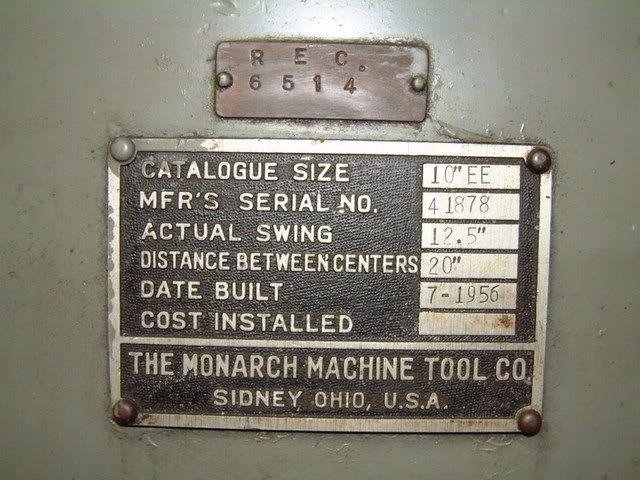
Here's a couple of pictures of my '56 10EE WIAD that I won at a local auction a few months ago.

DSCF2026.jpg


DSCF2027.jpg


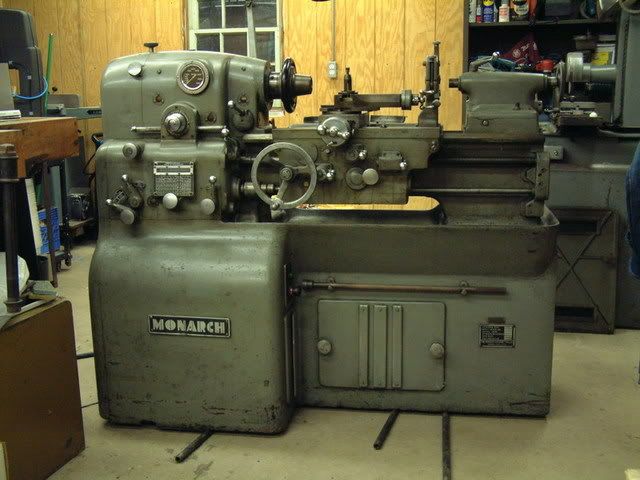
It's a long story, but some personal commitments kept me from spending any time with the machine until now. Obviously, it needs a really good cleaning and I'll start on that right away. My long-term plans are to partially disassemble, polish, and paint. Before starting that project, however, I want to work on any electrical gremlins that might be living in the machine. I would really like to keep the machine as close to original as possible, so I'd like to stay with the WIAD rather than converting to a VFD.

I'm a bit confused about the electrical hookup. The junction box (with disconnect) on the back of the lathe is for three phase power and has three fuses. My machine, however, doesn't have a coolant pump and, if I understand correctly from some of the other threads, doesn't need three phase power. If that's the case, which leads do I connect to? Here's a picture of the label on the junction box:

DSCF2028.jpg


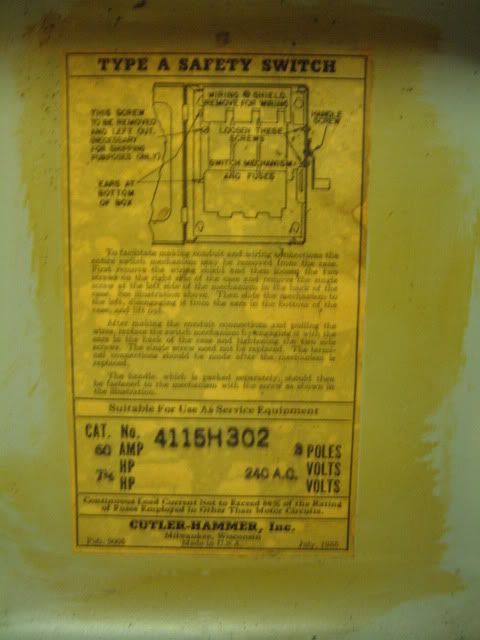
I'm sure I'll have more questions once I get the machine powered up!
 
"The junction box (with disconnect) on the back of the lathe is for three phase power and has three fuses. My machine, however, doesn't have a coolant pump and, if I understand correctly from some of the other threads, doesn't need three phase power. If that's the case, which leads do I connect to?"

A WiaD uses the Cutler-Hammer magnetic motor starter for both WiaD control and coolant pump protection (coolant pump control is by a separate switch, which your machine likely won't have); the WiaD has its own protection and it doesn't need or use the protection provided by the starter.

Just the same, the contactor, the coil, and the associated "three wire" control station (usually labeled Control Start and Control Stop, but sometimes labeled Motor-Generator Start and Stop) are part of the WiaD's primary circuit, as is the three-phase fusible disconnect.

The disconnect has to be there because the starter does not remove all machine power. There are still live parts within the machine even though the contactor is in the OFF position.

It is true that the WiaD needs only two poles, normally L1 and L2, to operate. However, on some machines, the "return" for the "three wire" control station is to L3, in which case the contactor may be rewired to use L1 and L2, and not L1, L2 and L3.

Once this step has been accomplished, the fusible safety switch may be provided with two fuses in the appropriate positions, and thereafter connected to your panel.

You probably can accomplish all of the above using visual cues, but a DVM which has a continuity checker function would be quite helpful. As, of course, would be the schematic diagrams for your machine.
 
Sometimes you can figure it out by tracing the actual wires from the disconnect over to the controls section, see where the AC power is being used and where the L1, L2, and L3 are landed...many times goes directly to a contactor or two (sorry not intimately familiar with the WiaD layouts) and you can "see" what's going on.

The L3 could be landed on a terminal in the controls section that is unused in your machine, should the coolant pump option be specified originally, or later as OEM/aftermarket, the terminal would be ready and waiting.
 
A coolant pump can be added later.

The sump is drilled and plugged for it.

Later Monarch kits used a flexible, metal reinforced hose, but earlier machines hard-plumbed the sump to the pump.

The pump inlet is obviously lower than the bottom of the sump, and the pump compartment likely will not be drilled and tapped for installation of the pump.

The pump itself is still available from BSM Pump, a successor of Brown & Sharp Pump. A model 200, if memory serves.

BSM offers a single-phase version of that pump, but the compartment which Monarch provided is too small for a single-phase pump. If you remove the capacitor from the top of the motor, the pump should fit, however.

I believe the original plumbing was 3/8", with an increaser at the pump inlet, and a union in between the 3/8" side of the increaser and the sump outlet.
 
I found it easier for me to use those little Giant submersable pumps instead of the stock pumps in the EE when I find it nessesary to have flood coolant.
I dont use flood coolant often enough to leave it in the machine, it gets nasty after a period of time.
 
Thanks for he help! I spent most of the weekend going through the wiring and making sure it matched the schematic. I was pretty worried when I removed the cover over the magnetic starter and found a bunch of wire nuts and electrical tape. Thankfully, it wasn't too bad - a previous owner had rigged up a transformer for a work light and all of the connections were made in the starter cabinet. That whole mess is now gone!

peterh5322: It appears that L3 in my machine isn't used for anything. The wire from the fusible disconnect is the only connection to this terminal on the magnetic starter. That being the case, it looks like I can remove the L3 fuse, hook up power to L1 and L2, and see what happens!

morsetaper2: I don't really know anything about the machine's history. It's possible that it's a Navy veteran since there's a number stenciled on the back of the machine. I plan to contact Monarch to find out more.
 
it looks like I can remove the L3 fuse, hook up power to L1 and L2, and see what happens
I don't know if you will be using utility 3ph or if you'll be running a RPC off of single phase. If the later is the case and you won't be adding a 3ph coolant pump, you should look into running directly off of single phase. Sounds like you're already on that track though.

Machine looks nice. Let us know how it runs.
 
"It appears that L3 in my machine isn't used for anything. The wire from the fusible disconnect is the only connection to this terminal on the magnetic starter."

Early machines returned the "three wire" control station to the B phase.

Late machines returned this to the C phase, thereby making it a single-phase machine if it has no coolant pump.

The work light transformer is often found inside the base, on the conduit for the speed pot.

This mixes low voltage high impedance wiring (the speed pot), 120 volt wiring (the work light), and 240 or 480 volt wiring (the line voltage).

Not the safest, nor the lowest noise design.

The small transformer within the main contactor housing is a 230:5 or 460:5 volt unit, and powers the pilot lamp within the CONRTOL ON button.

The lamp is a 6.3 volt unit, so this lamp should last a lifetime.
 
Lca078: Yes, I'm going to run directly off single phase.

peterh5322: Yep, the transformer that I removed was on the conduit for the speed pot. Almost all of the insulation had crumbled off the transformer's wiring and was sitting at the bottom of the housing. The sloppy way the thing was hooked up sure made it look like an afterthought. If I want a work light, I'll just plug it in to a wall outlet.

I was confused about the transformer in the main contactor housing - thanks for clearing that up for me. Where's the coil that, when energized, closes the contactors?


Back
Top