Joe--the job is easier than you think and it can be done in an afternoon or couple of evenings. Here's a few suggestions to help:
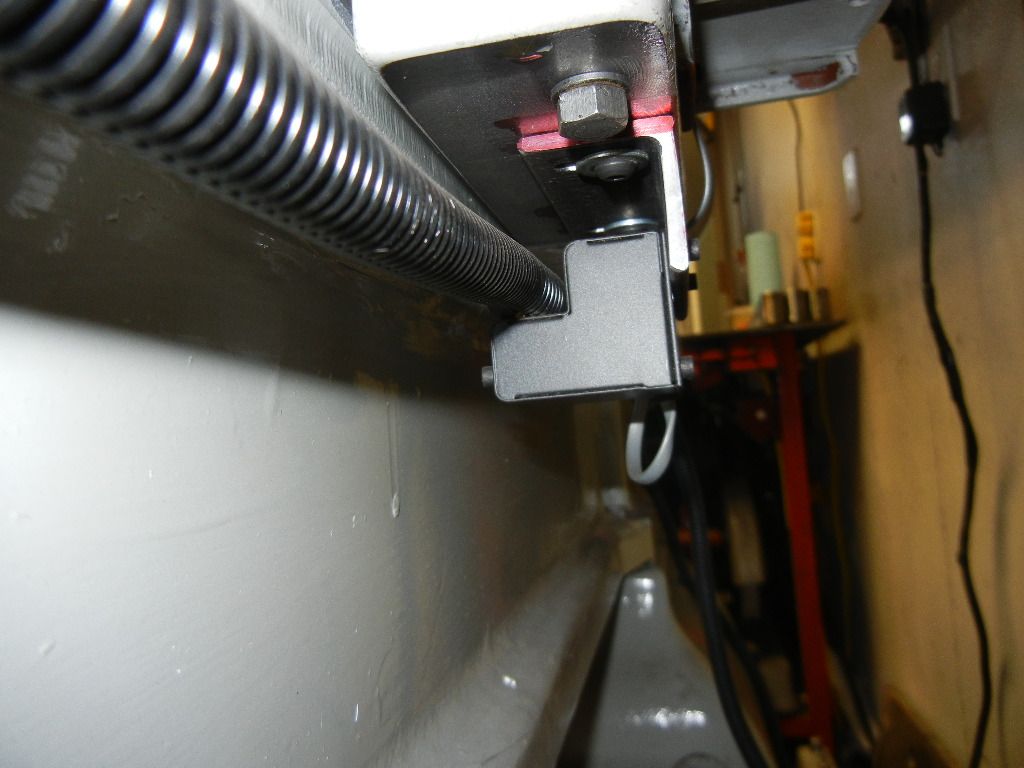
1) It's critical for the Shooting Star to have lines of travel in the same plane and height. Given that, you need a few reference points, luckily the underside of the bed is machined so the distance down from the bed can be accurately set. For the longitudinal travel of the apron I used it to build a jig to place against the underside of the bed and drill and tap into the bed for the standoff. It was a very simple a piece of 1 inch square the a hole drilled at the distance down I wanted it. Clamped it the bed then using a hand drill, drilled the bed and then tapped 10-32.
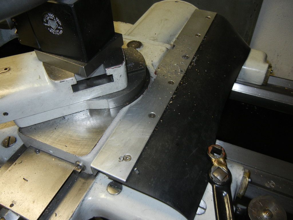
2) For the Cross Slide I put it on my mill zero'd off the dovetail and machined two lands for the standoffs for the DRO scale. You can see in the picture photos below.
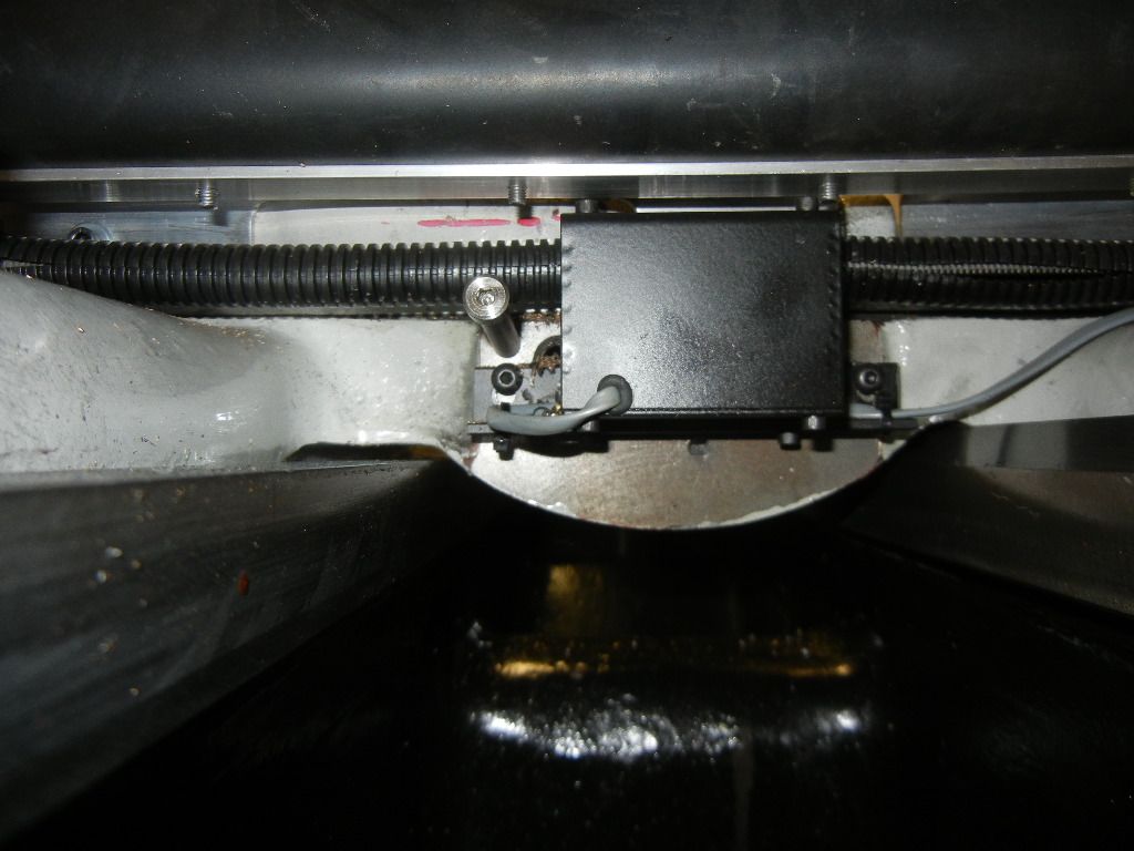
3) The next critical work is the attachment of the encoder. The Shooting Star comes with the specs and dimensions which makes the distance from the standoffs easy, its then a matter of machining the stand offs to equal length.
4) Now the you have the distance set there is one more to calculate and locate, that's the distance out from where you attach the encoder.
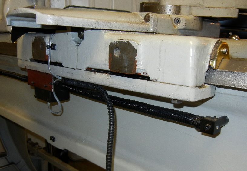
5) For the Apron travel I machined a clean surface on the underside of the piece that holds the apron down, then drilled and tapped for the encoder brackets. See photos below.
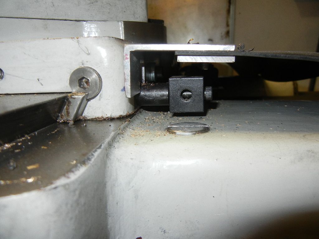
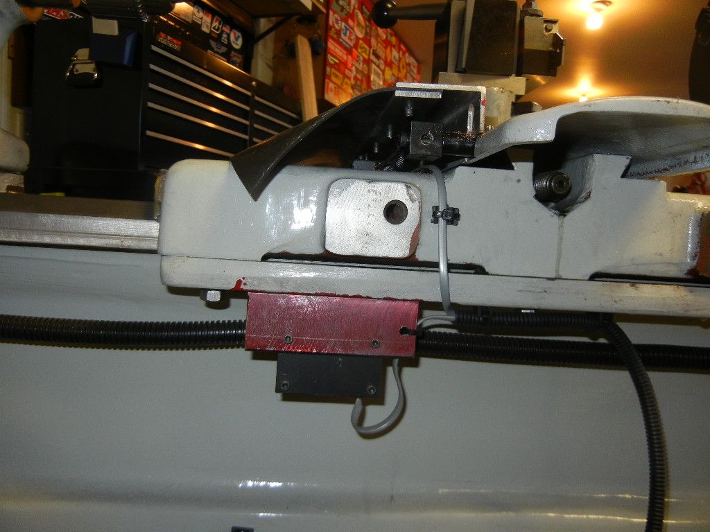
6) For the Cross Side travel I attached to the apron. ON mine it was already machined for the steady rest so it was just a matter of drilling and tapping.
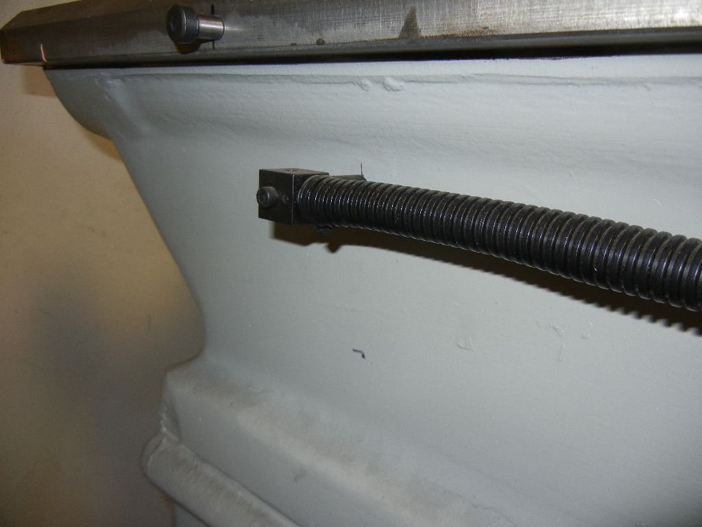
7) Note depending on the length of your bed and the length of the scale you may need to cut the scale or place a safety stop so the apron doesn't run off the end and cause a crash in either direction.
8) For the cross feed encoder you'll need to do the same, I used a Stripper Bolt (AKA Shoulder Screw) to prevent the tailstock from crashing into the encoder, remember the tailstock fits nicely between the apron rails. You will see it to the left of the encoder in the photos below.
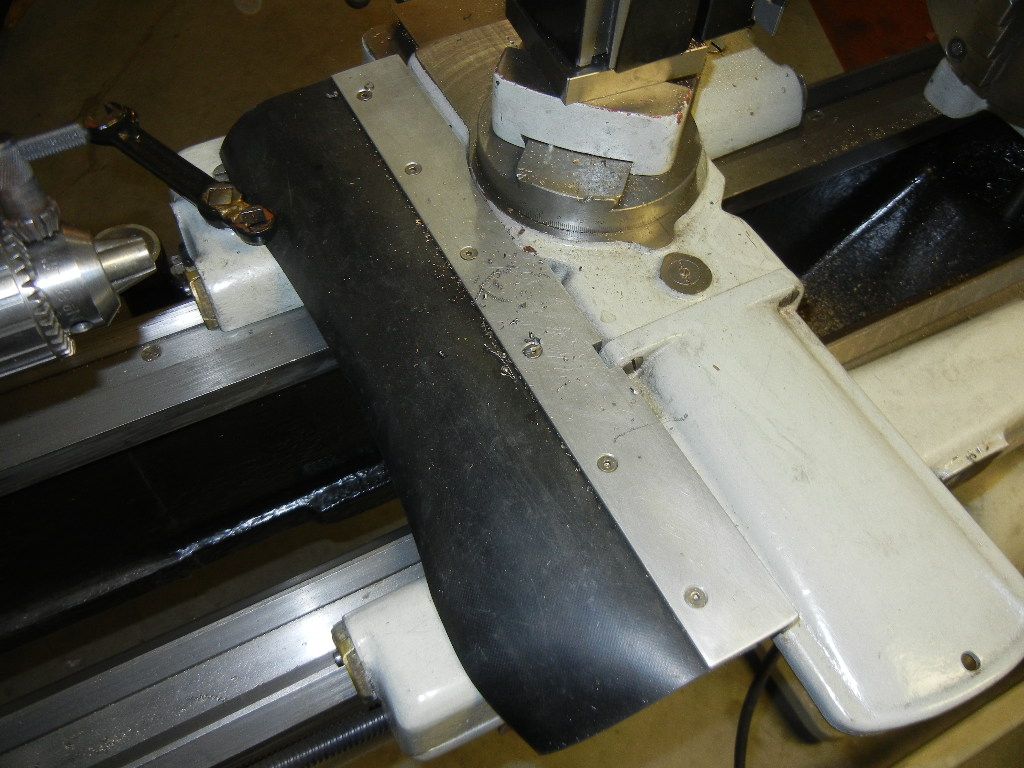
9) Lastly you need to fab up a cover to prevent chips, coolant if used, and oil from entering the works. I made mine out of aluminum and rubber.
Thats about it. If you have any questions don't hesitate to ask, happy to help. Cheers.