What's new
What's new

southbend accessory identification

jaxsin

Plastic
Joined
Sep 20, 2012
Location
Pennsylvania, USA
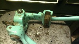
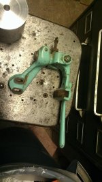
I have a 1934 Model 405 SB 9". I have this thing which I have no idea what it is. I am confident that it attaches to the cross slide where you would also attach a follower rest. I have looked at quite a few old SB pamphlets for accessories and have yet to see anything that resembles the part. Does anyone here have a definitive answer as to what I am holding onto?

IMAG0232.jpgIMAG0233.jpg
 
What you have is known as a "mica undercutter". It was an accessory used when doing armature service work on a lathe. In cases of DC motors and generators, there is a portion of the armature (rotating part) that has what is known as the commutator. the commutator is made up of copper bars, each diamerally opposite pair of commutator bars being connected to one of the windings on the armature. Carbon brushes ride on the commutators and current travels from the stationary brushes into the rotating commutator (or from it, depending on whether a generator or starter motor).

In service, the commutators get worn and spark pitted. When this happens the arcing of the brushes and brush wear accelerates. It is time to service the armature. This is done in the lathe. The first step is called "cutting the commutator", and consists of turning the comutator down to a true cylinder, free from chewed up areas. The next step is called "undercutting the mica". This is where the accessory you pictured comes into use.

The mica is insulating material between the copper commutator bars, run radially like wagon wheel spokes. The mica has to be "undercut" so a clear gap exists between adjacent copper commutator bars. The mica undercutter uses a thin saw blade with no set to it. It is mounted like a follower rest on the saddle of the lathe. To use the undercutter, you bring one of the mica strips to 12:00. Typically, you put the lathe in back gears at the lowest speed, and pull the belt by hand to get the mica lined up at 12:00. You rely on the gearing to hold things in position. NO POWER IS USED.
You then bring the saw blade down on the mica by pressing on the hand lever, and you crank the carriage to drag the sawblade thru the mica. You make a few passes so you get maybe 0.015-0.030" of undercut on a small armature's mica. You do this for each mica strip. When you are done, you
dismount the undercutter, and generally drag a fine scraper thru the slots to put a tiny chamfer on the corners. Lastly, you take the undercutter off the lathe and you polish the commutator using either a very fine commutator stone or perhaps a piece of canvas on a strip of wood.

This was commonly done in garages as older cars, trucks, tractors and motorcycles all had generators, and still have starter motors. The move to alternators on vehicle charging systems elminated the need for the undercutter. The move to permanent magnets in starter motors has largely eliminated the need for commutator work as well.

The other accessory that usually came with the undercutter was a tailstock chuck that ran on ball bearings. A lot of starter and generator armatures did not have centers in them. The "drive end" could be chucked in the headstock, but if the tail/commutator end had no center, then a tailstock chuck was used. Old garages had a lathe and had these accessories, along with an armature "growler" (for checking for bad windings).
 
Joe Michaels, Very good answer. Although I will add this was used on any AC or DC motor that had brushes.
Also, the cutting blade does not line up exactly 12 o'clock, it depends on the diameter of the commentator. And a small alignment blade is placed in the tool post. The height of this blade will aligned each segment with the cutting blade. Some alignment blades can also be used as a chamfering tool after the segments have been cut.
I have the same Micah undercutting tool and have used it many times. It is very handy when you're doing motor work.

Past eBay value up to approximately $150.

Note: Electric hand tools used to be labeled AC/DC. They dropped the DC part of the label many years ago. But you can still use either AC or DC on many motorized electric hand tools. The only exception would be the motors that have permanent magnets and that had variable speed control. I'm not sure how the variable speed controls would react under DC power.

promacjoe
 
Promacjoe:

Thanks for the kind words. I know that many appliance motors were "universal" motors for AC/DC operation. Things like vacuum cleaners (particularly the old upright vacuums) and some high speed appliance motors for blenders used brushes and commutators. AC repulsion-induction motors have commutators in various forms as well. I have a 3 HP open-frame R-I motor on my old Camelback drill press. When I first got that drill press, the R-I motor buzzed and had to be spun to get it to start. I cleaned the commutator and it started on its own, but the brushes were worn way down. I got new brushes, cleaned the brush holders, and stoned the commutator after the new brushes were installed. The new brushes cost 65 bucks, well worth the price. If anyone ever has to match up brushes for older motors or generators, Helwig Carbon is a great firm to deal with. Their engineers will not only match the brushes for sizing, but for carbon composition based on application.

Most electric hand tools of years ago had "universal motors", having brushes and made for AC/DC current. When I first got out of engineering school in 1972, the most common engine driven welder used in field construction was the Lincoln "Pipeliner" (or "Classic"). It had two receptacles which provided 110 volts DC power. People using the welder could run a grinder or drill and incandescent work lights, which was all they needed back then. Once variable speed power tools took over, the needs for AC power came with them. I believe the variable speed power tools are "AC only".

When I was a young person, there were "auto electric" or "ignition" shops and "armature shops" as well as "fixit" or "appliance repair shops" in just about every neighborhood. The auto electric or ignition shops repaired and rebuilt automotive starters and generators, as well as ignition distributors. The armature shops repaired and rebuilt electric motors of all the common types and sizes. The appliance repair shops repaired things like toasters, blenders, vacuum cleaners, and other small home appliances. They all did commutator work to varying degrees. All of that is gone now, as we live in a throw-away society.

All of the old auto and vehicle and equipment repair garages used to do their own armature work on starters and generators. There were special light duty machine tools built specifically for automotive armature service. The bigger shops had a lathe as they did other work such as making valve guides, water pump bushings, and other miscellaneous parts. The next step from the "hacksaw" type mica undercutter was a motor driven saw mounted on the compound of the lathe. It was a small high speed motor with an extended arbor, mounted on something like a milling attachment to adjust the height/depth of cut. The undercutting saw was basically a very small diameter slitting saw.

I was recently in an "independent" motorcycle shop in my area. As I walked in the door, I thought I'd walked back in time. The owner had a 9" South Bend Model A bench lathe, fully tooled. He was testing an armature from an older Harley generator using a "growler" and a piece of hacksaw blade. The commutator was chewed up, and the owner told me if the windings tested OK, he'd turn and undercut the commutator. The shop is heated with a plate steel wood stove, and has the old Harley service tools such as a crank truing fixture and wheel lacing stand. You just do not see that sort of thing much anymore.

I've done a few automotive started commutators in my time. I turned them true in my South Bend lathe. On one starter armature I did for a friend, there was no center hole at the commutator end of the armature shaft. Not having a free-turning tailstock chuck, I miked the journal and made a fixture. I put a center in a piece of mild steel, reverse it in the chuck and bored it for a "wringing fit" on the armature shaft journal. This let me support that end of the shaft with the tailstock center. Not having an undercutting tool, I took a piece of broken hand hacksaw blade and ground off the "set" from the teeth and used the side of the grinding wheel to thin the blade a bit more. I then used the piece of hacksaw blade by pulling it toward me and pressing down on the top (back) of the blade. I used the tip of a 3-corner scraper to put a small chamfer on each corner of the copper bars, and finished by polishing in the lathe with a piece of canvas on a stick, to take off any remaining burrs.

On the old "Airhead" BMW motorcycles, a Bosch starter is used. They seem to last forever as Bosch got the right combination of brush composition, brush loading and commutator. However, the bronze bushings the armatures run in do wear out. When I do a BMW motorcycle starter, I clean up the commutator while I have things apart. Newer BMW motorcycles went over to a "Valeo" starter with permanent magnets. The word is this starter is nowhere near what the older Bosch starters were. The permanent magnets are stuck to the core of the rotor with epoxy. Over time, the permanent magnets come loose from the rotor and jam against the stator and that's all she wrote. Some enterprising people came up with a retrofit starter. It is a brush type motor with copper windings, made by Nippondenso, same as is used on light truck engines. A new end bell and bendix drive to match the ring gear on the motorcycle engine are being produced. The result is a bulletproof starter that is actually a little lighter the original Bosch unit. Sometimes, the old technology proves to be the better technology. The permanent magnet design was supposed to get away from commutators and brushes but wound up creating more problems and total destruction when it fails.
 
Mica is undercut with a saw, either hand or powered. I think that this is a commutator stone holder. We always started with a stone to clean up a commutator, and used a lathe when the commutator was too chewed up for a stone. We'd finish up turning with undercutting the mica, then we'd deburr the commutator bars, then a light stoning to clean everything up. We'd finish with an air nozzle to be sure that all the copper dust was removed before we'd call the job complete.

Large commutators could be stoned while the motor / generator was under power since the stones were non-conductive and had wood handles - we always draped anything over about 125 VDC with rubber mats, and made sure that the motor was unloaded when we stoned them. If the motor didn't have good commutator access, then the only option was to do the job in a lathe.
 
Well thanks for the answer. What I can tell you is that the blade that would be held in the clamp part is movable parallel to the ways. It most certainly makes sense to me that it would be called a mica under cutting attachment now that you all have mentioned it.
 
Let me add a point to this discussion in case anyone should undertake refurbishing an armature. When initially cleaning up the armature in the lathe (with the end supported by the tailstock, of course) be sure to take VERY light cuts. I was renewing a hard to replace starter from my Triumph TR3 and got a little aggressive when making the cuts and the entire end of the commutator came loose, wrapping the commutator segments into a spiral, ruining the armature entirely. :bawling:

I learned an expensive lesson then.
 
Professor:

I can;t resist throwing this in: Re: Triumph TR 3.... I thought the "Prince of Darkness" (Lucas) had provided electrics for the Triumph cars and motorcycles, and implanted electrical gremlins. That being the case, it would account for excessive wear on the starter commutator, endless grinding away trying to get the car started. When I was in engineering school (1968-72), some of my classmates had Triumphs, MG's, and a lone Austin Healey. All of them had electrical problems on a continual basis. To get in any of those cars and get them started without a struggle was the exception. I rode Triumph and Norton motorcycles, which were a shade better. That was 40 years ago.

Recently, a friend was given some basket case British bikes from the 50's. He chose to reassemble a Triumph "Thunderbird" motorcycle, his first time around British bikes and British electrics. It had the old Lucas magneto for ignition and Lucas "dynamo" to charge the battery for lighting. I told him to sell the remains of the Lucas magneto and dynamo, and put in a Joe Hunt magneto, and to go to an alternator retrofit for the lighting/charging system. I told him about the Prince of Darkness and told him if he wanted to ride that old Triumph, he'd do well to s--tcan the Lucas electrics. He did just that and has a Triumph that starts on the first or 2nd kick.

As for my college classmate with the Austin-Healey, he got pretty disgusted with it in short order. Parts, even in 1969, were hard to come by. The electrics were forever leaving him stranded or looking for someone to give it a jump start. Push starting on city streets rarely worked. The A-H owner finally got so fed up that he bought the engine, tranny, and driveshaft out of a wrecked Volvo sport model ( P 1800, IIRC). He ripped the A-H engine and tranny out of the A-H, and cobbed in the Volvo engine and tranny, salvaging the driveshaft front yoke/U joint and making up a "compromise" driveshaft to use the A-H rear end. Once he got the Bosch electrics in that A-H, it was like night and day. The thing started reliably and never left him stranded again.

Another guy in engineering school decided he wanted to own an E type Jaguar. He found one within his price range, so it had some years and miles on it and had "issues". Being a typical mechanical engineering student of that era, he figured he could get things straightened out and have a good Jag. Wrong. Endless trips to the foreign car junker and endless trips to imported car parts places and going bankrupt was what that Jag did for him. He had bought it thinking he'd have what, today, is called a "chick magnet" aside from a fast, well handling sports car. He had anything but. He finally got so mad at that Jaguar that he ripped out the Jag's engine and tranny and cobbed in a small block Chevy V-8 and four speed tranny. It was a cob job with a lot of wires dangling and some interesting fabrication for the accelerator linkage and motor mounts and tranny mounting, but it worked. This was back when MIG welding was just coming on the scene, so for light/thin metal fabrication the options were limited. It was stick welding and oxyacetylene welding or brazing, and it was also a case of whatever materials could be begged, borrowed or stolen. But, with the small block Chevy engine and tranny, the Jag was suddenly a reliable and easy to maintain car.

We used to joke that the reason the British drank their beer warm was because the Prince of Darkness had provided the refrigerators and wiring. In the late 60's and early to mid 70's, people around me who owned British cars seemed to spend a disproportionate amount of time either trying to get them started or fixing them. We were young and crazy back then, and working on next to no budget and using junkyard parts and whatever else we could come up with was the norm. I think today's young people are missing a great learning experience as cars are absolutely bland and generally quite reliable, if not impossible for the average owner to repair or work on.

BTW: When I turn a commutator, I use a sharp "vee" toolbit much like a threading toolbit. I stone the nose to the slightest radius and stone the cutting edge to make sure they are absolutely sharp. As you noted, I take very light cuts. If you look at how an armature is made, the commutator bars are held in place by "banding". This is sometimes twine wound under tension, tied off and varnished with insulating varnish. Sometimes, a thin collar made of insulating material is driven over the ends of the commutator. Either way, not too much is holding the commutator bars in place. They have to be insulated from each other and from the shaft. If a toolbit takes too deep a cut or digs in, it can loosen or peel the commutator bars off.
I set my toolbit exactly on center, and make sure it is freshly stoned anytime I touch up a commutator.
 
wow.
i feel educated.no sarcasm intended,this stuff i can really use.
i have two starters that need a little work,this thread will be greatly helpful.
one starter is from a 27 studebaker,and its not the z shaped one that goes through the rad.that is what i would consider an ornament.

to the op-wish i had that attatchment.
but the previous owner said he has some kind of odd rest for it.but cant find it.i'm hoping thats what he was describing.
 
LOL.

What joe did not describe was the "voltage regulator" setup on those lucas systems in motorbikes.
This was nothing more than a large, total loss, 50 watt zener diode, clamped right between the
buss voltage and ground.

The 50 watt rating meant that the total range from no load, to full load, had to be less than 50
watts.

Because the headlight and tail-light together added up to about 55 watts, and there were a few
amps drawn by the ignition circuit, it meant that these bikes were guaranteed to have a dead
battery in a week, as most states now require headlights on at all times.

Truth be told, I owned a BSA 650 thunderbolt (single carb model) and enjoyed running it.
When I bought it the previous owner had about six batteries alongside the bike in the garage.
Always a bad sign. Never trust a motorbike with an ammeter in the headlight. It's there for
a reason.

I gave up on Lucas-equipped bikes in favor of the Bosch types. Much happier ever since!
 
Professor:

.... I thought the "Prince of Darkness" (Lucas) had provided electrics for the Triumph cars and motorcycles, and implanted electrical gremlins. .

OT - One of the funniest Ebay auctions I ever saw was for a "Genuine N.O.S. Lucas Electric Smoke Replacement Kit for British Cars". Very professionally printed label on a bottle of Lucas Replacement Smoke. For use after all the smoke had leaked out of your Lucas electrics.
 
LOL.

What joe did not describe was the "voltage regulator" setup on those lucas systems in motorbikes.
This was nothing more than a large, total loss, 50 watt zener diode, clamped right between the
buss voltage and ground.

The 50 watt rating meant that the total range from no load, to full load, had to be less than 50
watts.

While I agree that the Lucas systems were a bit of a (bad) joke, the 50 watt rating on the Zener diode only affects how much excess voltage could be dumped through the diode without burning it out. The current/power draw of the bike itself is not limited by the diode. In fact, as the bike draws more power, the voltage from the generator will tend to drop, lessening the load on the Zener diode.


Back
Top