What's new
What's new

Drum switch for 1ph 220 system

JWPage

Aluminum
Joined
Apr 12, 2010
Location
Northern California, USA
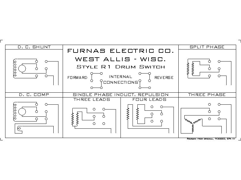
So I keep moving on with my rebuild on my 16" lathe, and decided to take a look at the drum switch. I noticed that 1/2 the mounting points were broken off, and surprised that it didn't short out.
So started looking for a replacement. Short story. Can't find the thing.


Went to my local electrical supplier, he was no help. Grainger, they tried but only had reversing drum switches.

This is what I have.

1 phase 220 supply.

A motor that has only two wires coming out of it.

220 supply SWITCH MOTOR

WHITE------------------1 A------------------------p
GREEN------------------2 B--------no connect B (motor wiring)
BLACK------------------3 C-------------------------P

I have a 3 position switch left, center, right.
Center all power disconected,

Left (high speed) 1=A, 2=B, and 3=C Full 220 to motor.

Right (low speed) 1=A, 2=C, and 3=B only 120 to motor, so it runs at 1/2 speed.

Questions: Is this correct? As the "B" wire was just hanging there and not connectted to anything. If it was it would cause a short.

Does anybody no where to find a replacement switch?
Thanks always.
 
Umm, cutting the voltage in half won't change the speed of an AC motor (directly). The frequency sets the speed of an AC motor, nothing else. That's why we use Variable Frequency Drives (VFD) to get variable speeds from AC motors.

Reducing the motor's voltage will change the power the motor can create, reducing it by a huge margin. If there is any load on the motor it will run more slowly, of course. This is because it hasn't got the power to run at the proper speed. It will probably burn out if run on low voltage under load for any amount of time.

That said, you may well have a 2-speed motor, or a reversible single phase motor. Does it have a nameplate on it? Can you provide a pic of the nameplate?
 
Now I am more confused than before.
Here is a photo of the motor. I don't see any markings
Only 4 wires come out of it. Two are wired together and the other two go to the drum switch. In one position 220 is applied to the wires, the other 120. As the other hot lead is swapped with ground.

1250-motor.jpg
 
Now I am more confused than before.
Here is a photo of the motor. I don't see any markings
Only 4 wires come out of it. Two are wired together and the other two go to the drum switch. In one position 220 is applied to the wires, the other 120. As the other hot lead is swapped with ground.
Well, with 4 wires coming from a single phase motor there are really only two possibilities:
1) Dual voltage motor; or
2) Single voltage reversible motor.

The wiring as you have described indicates that you've probably got a dual voltage motor wired for "high" voltage, in other words, the two windings are connected in series.
Were a motor like this wired for "low" voltage, you'd have the four wires from the motor connected in two sets of two with one wire from the drum switch connected to each set of two, making two bundles of three wires each. This sets the windings up in parallel.

How did you determine this is supposed to be a two-speed motor? It really seems to be a single speed motor, that the previous owner found could be run slower by operating at lower voltage (because it would not be powerful enough to run at the proper speed). Is there a capacitor can "hump" on the outside of the motor somewhere?

I didn't see a data plate on the motor in the pic you showed. I didn't even see anyplace for a data plate to be attached. Can you see around the back side of the motor, even using a mirror? Also, sometimes the data plate may be on the back end bell of the motor, opposite from the shaft end.
 
Drum Switches are made to be somewhat universal. A single model switch can be used for a variety of motor types, two phase or three phase, etc. Here is a hookup drawing from mine.

DRUMSW1.bmp


This is not the full range of hookups possible.
 
I prefer to draw the switches as regular, three pole, two position, center off
switches as a EE would do. This reduces the 'what goes where' effect.

Also there is 'stuff' inside the motor. Unless you know what the stuff is, and
how it connects, there is zero chance of getting the thing to run right.

An example of single phase, 240 wired capacitor start motor:

wire.jpg


In this case the run windings are in series to make it 240 volt, but the
start winding is single-voltage so that is returned to the centertap
between the run windings.
 
Well I couldn't find it, so I pull it out.
1277-motor-id-label.jpg

Here are a few other shots.
Here is how it was wired. 4 wires come out of the motor, 2 are connected together, and 2 go to the drum switch. The 3rd wire from the drum switch is not connected to anything.
1250-motor.jpg

This shows the 4 wires on the motor better.
1281-four-wires-2-contected-together-other-2-go-switch-3rd-wire-switch-not-connected-anything.jpg

Heres my drawing of how it was wired.
1280-drawing-out-wiring-diagram-power-comes-right-left-goes-motor-colors-tell-me-what-happening-3-positions-slow-off-high-slow-sends-110v-motor-high-sends-220v-off-send-nothing.jpg

Thanks for any help.
I notice that the motor shaft slides about 1/2" That can't be correct. I may be just replacing it with a modern motor and switch. Any comments on that?
 
Well looking at the label on the motor "Repulsion Induction" (thought it was the maker) and not a type, and the drawings above.
I am guessing that mine should be the 5th drawing. "Repulsion Induction" 4-wire, 1 phase.
So if I wire as about, what would I except the switch to do? Slow-Fast? Forward-Reverse?
 
Now would be a good time to wish-list what you want that motor to do, and perhaps it's the wrong motor?

If you want reversible and variable (or two-three speeds), that would be a VFD and a three-phase motor.

Before you spend any money making that motor 'work', are you sure that motor will satisfy your needs/wants?
 
1HP should be big enought, reversable would be nice, and dual speed not as much, as I can change belts to change speeds and use back gear.
So a reversing motor sounds like a good idea. Doesn't it?
Have not even looked at what a VFD, 3-PH, and new motor would cost. I am guessing over a $1000 when all done. Which is not that nessasary for what I will be doing.
 
So if I wire as about, what would I except the switch to do? Slow-Fast? Forward-Reverse?
The motor you have is a single speed, single direction, dual voltage motor. The switch can only turn it on or off. The two wires that are hooked together set the voltage to "high", ie, 220V. If you were to run this motor on 110V, you'd wire 4 motor leads into two bundles of 2 each. To reverse the motor there's probably a set of brushes in the end bell opposite the shaft that can be rotated, if I understand R-I motors correctly.

The wiring diagrams shown for the Furnas switch as sketched by EPAIII are from an earlier time, when people were expected to be more careful than they are now. You'll see that one wire going into the motor is always "hot" which is really not the best idea.

To add more confusion, there are 2 different types of drum switches. There are 3-phase drum switches (which can also be used on single phase) and single phase drum switches. The sketch provided by EPAIII is a single phase drum switch. Your sketch is a three phase drum switch. Note the differences: there are only two lines that connect three terminals each in EPAIII's sketch while there are three lines that connect two terminals each in your sketch.

The best way to wire this, if you use a single phase drum switch as shown by EPAIII, and referring to your sketch for orientation, is:
One Motor wire to Top Left screw
Other Motor wire to Bottom Left screw
then,
One AC wire to top right screw
Other AC wire to bottom right screw.
then,
Ignore center left & center right screws.
then,
Ground wire from AC cord directly to motor, not through switch!

With that arrangement, you'll have On-Off-On switching with the drum switch, which is all you can get from your motor.

If you use a 3-phase drum switch, as you show in your sketch, everything stays the same, except you'll need to change the jumpers (shown in brown on your sketch) so they don't cross over. You'll then have the same On-Off-On control.

PS, lots of folks like the R-I motors as they've got good characteristics to run a machine tool.

PPS, the shaft will center up when the motor is running. The magnetic fields inside will hold it in place.
 
This motor is a duel voltage meaning it can be wired for 115v or 220v at 115v it will draw 14 amps and 220v it will draw 7 amps. I is not reversable and you cannot vary the speed by changing voltage. true if it is wired for 220v and you hook it up to 115 it may run slower expecially under load however you risk burning the motor up and possible a fire because the field windings cannot develop an adaquate magfetic field so motor will have to work much harder to achieve the desired output power thus more heat.

There are good single phase 220v reversable motors out there although i prefere 3 phase. you could wire this motor for 220v and run it that way but you would not have a reverse. I would replace with a reversable single phase or a three phase motor.
 
I was asked how I know this is a single speed motor. It's easy, the motor data plate shows only one speed, that is, 1750 (or perhaps 1730) RPM.

Reversing: I've got a lathe that has forward and reverse through a clutch system. I have only used reverse a very few times, when cutting metric threads. Not having reverse is really no big deal, in my opinion. If I didn't have reverse I would have shut off the spindle and turned the chuck backwards by hand until I backed up enough to take another cut.

On this lathe, the easiest way to get variable speed, and reversing, would be to use a 3-phase motor and a VFD. In general VFD's require a three phase motor (*), which lets the motor be easily reversed by the VFD. The VFD will be able to use single-phase input current, making it easy to use in a home shop setting.

A 1HP 3-phase motor should be pretty cheap to buy. A 1.0 or 1.5 HP VFD should be pretty inexpensive, too. Have a look at Surplus Center. Then it's just a matter of wiring up a speed control knob and reversing switch from the VFD's control connections to a handy place on the lathe. Do note, the VFD is to be connected directly to the 3-phase motor!

I don't have any VFD equipped machines as I've got utility 3-phase power, so I'm not the best expert on them. A search on the forum should bring up a lot of information.

Another choice would be to get a reversible single-phase motor. I believe Grizzly (a forum sponsor, I believe) sells these new, among other dealers. Presumably a new motor will come with wiring directions.

(*) There are single-phase VFD's available. They're pretty uncommon. They cannot reverse the motor directly. They're more expensive than 3-phase VFD's.
 
Information overload!
Too many choices. But thanks for the info. How did we do this research stuff before the Internet?
A comment another person, made me think that reversing may not always be a go idea. I have a screw on lathe head, and the concern could be that in reverse the chuck could spin right off the spindle. And the fact, that there are few times that I would need it.
I'm guessing just a normal 1-ph 220v sigle speed motor with just a simple on/off switch should do.
But they a varible speed motor sounds like a good idea.
So maybe the VFD and a 1HP 3-ph motor may be a good solution, just not using the reversing feature.
Was not clear if the VFD is a 1-ph device or a 3-ph device. Or if it convert 1-ph to 3-ph. Or if that model is uncommon, and therefore it would be better to use a phase-converter (1-ph to 3-ph) then input that into a 3-ph VFD that goes to a 3-ph motor.
 
A VFD will take whatever it tolerates and turn it into DC voltage, then chops it up into a "frequency". It's a messy "frequency", but it works.

So, any VFD that takes three phase input, has three AC to DC power supplies. Inverter or transformer, it doesn't matter, it CAN take the three phases and make the changes.

SOME VFDs have beefy power supplies and can take single or three phase power and no de-rating is needed. That is always indicated in the sales literature.

OTHER VFDs can take single or three phase power, but the power supplies are not so beefy, and single phase input will obligate a de-rating of the motor capacity. That is not always indicated in sales literature, but a call to the maker will clear up which unit would accept single phase at the desired horsepower rating.

Some will say a 33% derate, others might say a 50% or 66% derate. Ignore them and ask the manufacturer.


Back
Top