I've found that the base of my tailstock is pretty worn. The groove in it is maybe 0.020" so it doesn't line up with the center of the part. While shimming it is certainly an option, I was wondering if anyone had ever drilled/tapped some set screws into the front of the base to adjust the height that way?
How to install the app on iOS
Follow along with the video below to see how to install our site as a web app on your home screen.
Note: This feature may not be available in some browsers.
Largest Manufacturing Technology Community on the Web
Stay Connected:
You are using an out of date browser. It may not display this or other websites correctly.
You should upgrade or use an alternative browser.
You should upgrade or use an alternative browser.
Fixing tailstock tilt
- Thread starter hackish
- Start date
- Replies 18
- Views 2,753
thermite
Diamond
- Joined
- Sep 21, 2011
I've found that the base of my tailstock is pretty worn. The groove in it is maybe 0.020" so it doesn't line up with the center of the part. While shimming it is certainly an option, I was wondering if anyone had ever drilled/tapped some set screws into the front of the base to adjust the height that way?
WTF?
I surmise it would be KINDER to drive the sort of thin bamboo splints under it that ancient Chinese torturers drove under a victim's fingernails and toenails to make them "line up" more cooperatively...

Last edited:
iwananew10K
Diamond
- Joined
- Sep 12, 2010
- Location
- moscow,ohio
With just a little understanding of what you are doing and a little practice it's not a huge undertaking to do it "right"....its a old file into a hand scraper territory....very small area to deal with....likely the only thing you need you don't have is some hi-spot blue....in this case no shame in making the base sit right and then shimming to height.
You CAN do this.
You CAN do this.
Richard King
Diamond
- Joined
- Jul 12, 2005
- Location
- Cottage Grove, MN 55016
First you have to tell us your skill level, a Beginner or have some more equipment like a milling machine. A few picture would help us here. You can use your cell phone or a digital camera. The set screw idea isn't something most of us would never do. We hope your not sweeping the tailstock OD or ID using a long skinny bar?
Have a manual and did you level / align the bed before sweeping the tailstock?
As Iwana said it's pretty easy to fix it the right way or get it close if it's low .020 and your using it.
Give us some more info and a few pictures and most of us will be happy to help you and not insult you. :-)
Have a manual and did you level / align the bed before sweeping the tailstock?
As Iwana said it's pretty easy to fix it the right way or get it close if it's low .020 and your using it.
Give us some more info and a few pictures and most of us will be happy to help you and not insult you. :-)
First you have to tell us your skill level, a Beginner or have some more equipment like a milling machine.
I don't know if it's under-reporting to say I'm a beginner. I have some machining experience and a lot of mechanical and engineering background. I sold my bridgeport years ago and bought a little toy china-mill. It's a Precision Mathews, so it's not the crappiest thing out there. This is the first lathe I have ever owned. It was reported as freshly rebuilt by someone's grandfather who was apparently a machinist. It looked clean, I did a few basic checks and trusted the story as it wasn't mounted and I couldn't run it.
Unfortunately I had to rebuild the apron since it was so poorly adjusted that the gears were binding on the worm gear and it wouldn't shift into auto-feed. The split nut is pretty badly worn, but I was able to cut a reasonable set of threads. This evening I decided to stick an indicator on the chuck and found it had about 0.025" runout. I will probably turn the backplate true next time I have a chance.
As you can gather, the machine has some deficiencies that I'm trying to address/tune up, but at least it's pretty with a new coat of paint
")
A few picture would help us here. You can use your cell phone or a digital camera. The set screw idea isn't something most of us would never do. We hope your not sweeping the tailstock OD or ID using a long skinny bar?
Have a manual and did you level / align the bed before sweeping the tailstock?
I'm not sure I follow what you're suggesting. I stuck a center in the tailstock and turned a point on some material, then set about matching the 2 points. Since the tailstock sits on the little way I assume it is aligned. I managed to shim it up so I could centre drill the part I was working on, but since it has a bit of a tilt, it needs a proper fix. I noticed the handwheel has been hacked up with a nail (I assume it should have either a set screw or a tapered pin).
As Iwana said it's pretty easy to fix it the right way or get it close if it's low .020 and your using it.
Give us some more info and a few pictures and most of us will be happy to help you and not insult you. :-)
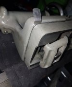
Photos are attached. Seriously, that is a nail holding the handwheel in. You can see the amount of wear on the base. The ways don't look terrible, but I don't know if someone just stoned them to make them look good. Part of getting the tailstock all trued up will be to do a more thorough examination of how true it actually is. I have a nice 1" drill rod just waiting for the task.
Attachments

Richard King
Diamond
- Joined
- Jul 12, 2005
- Location
- Cottage Grove, MN 55016
It's getting late and I am getting up early. If I were you I world check the quill tightness in tailstock. see if it is loose and thats whats pointing down. can check that by setting a mag base on top of TS and indicator on quill next to TS base and try lifting and check for slop. Then set the mag on the compound and indicator on top of quill and indicate the top of quil moving criss slide in and out to read top dead center of quill (oh with TS locked to bed and quill screwed out say 4" and lock on.) then move the saddle back and check check top of quill the same way but on TS end of quill. Then dismantle the TS and flp the bottom 1/2 upside down on you PM mill in indicated in vise. see what you get. I have to get to bed. Have fun
thermite
Diamond
- Joined
- Sep 21, 2011
I don't know if it's under-reporting to say I'm a beginner. I have some machining experience and a lot of mechanical and engineering background. I sold my bridgeport years ago and bought a little toy china-mill. It's a Precision Mathews, so it's not the crappiest thing out there. This is the first lathe I have ever owned. It was reported as freshly rebuilt by someone's grandfather who was apparently a machinist. It looked clean, I did a few basic checks and trusted the story as it wasn't mounted and I couldn't run it.
Unfortunately I had to rebuild the apron since it was so poorly adjusted that the gears were binding on the worm gear and it wouldn't shift into auto-feed. The split nut is pretty badly worn, but I was able to cut a reasonable set of threads. This evening I decided to stick an indicator on the chuck and found it had about 0.025" runout. I will probably turn the backplate true next time I have a chance.
As you can gather, the machine has some deficiencies that I'm trying to address/tune up, but at least it's pretty with a new coat of paint
Seems you have "enough" background - and personal initiative - to "get 'er done", then.
It will help others to help you if you dig deep into PM's several TS-rebuild threads - most any "split" 2-piece TS, any make of lathe, is done the same way, so you'll "get it" as to where Rich is guiding you from a 10EE or SAG Graziano TS rebuild as easily as a SB one.
"In the meantime"... two things:
- assessing the bed condition is crucial. If it is badly and unevenly worn or significantly out of true, "twist" wise, you can NOT reliably sort the TS (or anything else) to "repeat" reliably at different positions.
- You have only the one lathe and the one.. millish-thing.
You'll want to be able to make a few things whilst the restoration proceeds.
Consider acquiring a small boring head, Criterion, used, or Criterion-knock-off, new. These have threaded "tails", and (some of) those tails are CHEAP. Probably an R8 suits the PM mill, 2 MT for the lathe TS.
Now.. "old trick" for FUBAR TS on a "company lathe" a Machinist (Union Shop..) was not PERMITTED to rebuild, was to put a boring head into the TS, mount a stub center or bushing with a center-drill set into it, Weldon-style flat & setscrew, and then..
"Clock" the boring head slide at an angle to where it could compensate for BOTH vertical and horizontal error and "dial in" the needed on-axis or geometric center with the slide mechanism of the boring head.
Also wants a rod or such to prevent rotation, but voila - most boring heads already have a transverse mount hole for axial cutters anyway, so that isn't hard to rig-up.
This .. is a "monkey patch". No argument.
BUT not only can it "get you by", it can also be used to set-over for turning tapers, error compensation included.
And it is still a boring head for a mill. Which you happen to have.
Little or no "waste" in the spend, IOW.
Even if.. you find the best way forward on this lathe is .. to trade it for a BETTER one.
jim rozen
Diamond
- Joined
- Feb 26, 2004
- Location
- peekskill, NY
The wear on the TS underside is not 0.020 deep.
The axial lash in the handwheel indicates something is assembled wrong. This
should be easy to fix.
The tailstock ram tilts 1/8 of an inch down when fully extended, right?
Oh, my mistake. It tilts 0.001 inch down when fully extended.
Possibly somewhere in between. Let us know.
The ram will have about two thou of slop in the TS housing. That is, it will shift
up down side to side by around one or two thou. This is about normal for a machine
in this condition. DO NOT TRY TO FIX THAT NOW.
DO NOT DRILL OR TAP the tailstock castings.
Clean it. Fix the axial lash in the handwheel. Separate the two halves of the
TS and install brass shim to bring the ram near center and more or less horizontal.
Run the lathe. If this machine is not accurate enough for drilling 0.005 inch diameter
holes then buy a better one, if this is what you need.
The wear on the TS underside is not 0.020 deep.
The axial lash in the handwheel indicates something is assembled wrong. This
should be easy to fix.
It wouldn't be out of character to find yet another thing incorrectly assembled with this. I'll tear the TS down and see if I can figure out what is incorrect or missing.
The tailstock ram tilts 1/8 of an inch down when fully extended, right?
The 0.020" spec was just an estimate. I could measure it accurately, but fully extended it was around 3/32" off the center of the part I was turning. Before continuing with that, I decided to verify the chuck. It's off, so I decided it was best to fix that first. The backplate is machined to match the chuck but the machined lip is not true. I don't know how someone managed to do that! I'll likely just machine it smaller and then nudge the chuck until it runs true.
Clean it. Fix the axial lash in the handwheel. Separate the two halves of the
TS and install brass shim to bring the ram near center and more or less horizontal.
Run the lathe. If this machine is not accurate enough for drilling 0.005 inch diameter
holes then buy a better one, if this is what you need.
Given that the wear has caused a tilt, would it be more advisable to have the base ground flat then shim the entire thing up? The TS is designed from the factory so it can be offset. While I could turn a stub to put my boring head in, I prefer to avoid such hackery if I could.
iwananew10K
Diamond
- Joined
- Sep 12, 2010
- Location
- moscow,ohio
If you cut the point of your center in-situ the chuck has no bearing....cutting it in-situ removed chuck error.
jim rozen
Diamond
- Joined
- Feb 26, 2004
- Location
- peekskill, NY
"Given that the wear has caused a tilt, would it be more advisable to have the base ground flat then shim the entire thing up?
Do not remove any metal until you are certain of the problem. You can always take the shim out. Once you start
taking metal off the TS base you cannot put it back on.
Do not remove any metal until you are certain of the problem. You can always take the shim out. Once you start
taking metal off the TS base you cannot put it back on.
I'm probably being too anal with such an old machine. In any event, I managed to get it under 0.001" where it had started at 0.027, so I'm back to working on the TS.
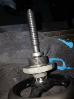
The nail has been removed from the handwheel. I suspect this once held a tapered pin, but you can see someone made a mess of drilling it out.
There is considerable gap and I'm not sure if it is a missing washer - I don't see one in the parts diagram. Neither shows evidence of a lot of wear either. Possibly the handwheel isn't even for this machine.
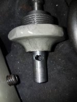
The tapered part fits snugly in the TS casting. There is a huge amount of play on the screw. How much is acceptable?
The nail has been removed from the handwheel. I suspect this once held a tapered pin, but you can see someone made a mess of drilling it out.
There is considerable gap and I'm not sure if it is a missing washer - I don't see one in the parts diagram. Neither shows evidence of a lot of wear either. Possibly the handwheel isn't even for this machine.
The tapered part fits snugly in the TS casting. There is a huge amount of play on the screw. How much is acceptable?
Attachments
Mine was about .015 low when I acquired the lathe.
I thought the same as you- mill the base flat- but realized, what about the v-way wear? Mine shows a light line on the way that can be felt, but no flat at the top that would indicate excessive wear like you'd see on the front sadle v ahead of the chuck. I suppose "tilt" could be easily measured simply by indicating across the disassembled base at the very end of the bed where there would be no wear. Of course, as wear varies down the bed same as for the saddle the spatial relationships will vary at different locations.
My thinking was shimming would obviously compensate for height , and while "tilt" can't be "fixed" without milling, scraping, etc., that it didn't matter because the center of the tailstock needs to be aligned to the axis of rotation at only one spot.
So long as it is correct height at the centerline of the axis of rotation- which can be accomplished by shimming, being low/high on either side doesn't matter UNLESS the tailstock is intentionally offset. I never turn tapers long enough to need this, and the boring head setup Thermite spoke of will suffice if I need to at some point; I've read about this before but can't reconcile how it could be removed from the tailstock and replaced with precise repeatability.
Meantime, I'll search for these rebuild threads to see what's involved in doing it "right".
My thinking was shimming would obviously compensate for height , and while "tilt" can't be "fixed" without milling, scraping, etc., that it didn't matter because the center of the tailstock needs to be aligned to the axis of rotation at only one spot.
So long as it is correct height at the centerline of the axis of rotation- which can be accomplished by shimming, being low/high on either side doesn't matter UNLESS the tailstock is intentionally offset.
You can shim the front or back of the tailstock and get the tilt and height correct. I was considering just tapping a screw in there so I could easily adjust it, but listening to the advice here, I decided to just shim. The part I wanted to avoid was having the shim walk around and thus be slightly different each time the tailstock was loosened and moved.
Richard King
Diamond
- Joined
- Jul 12, 2005
- Location
- Cottage Grove, MN 55016
Once you get it right you can 1/2 ass epoxy in some grade linen phenolic shim. it comes in different thicknesses. Mc Master Carr sells it. roughen one side and leave the other alone.
thermite
Diamond
- Joined
- Sep 21, 2011
You can shim the front or back of the tailstock and get the tilt and height correct. I was considering just tapping a screw in there so I could easily adjust it, but listening to the advice here, I decided to just shim. The part I wanted to avoid was having the shim walk around and thus be slightly different each time the tailstock was loosened and moved.
UNTIL.. you get the bed corrected, you'll need a different height at any of several points in any case. Not an "infinite" number. Not every 1/4" of movement. Just more than one or two.
Makes more sense to be able to just move the tip of the center.
5 MT TS, 12-foot bed, we'd slide paper foil torn off a pack of Camels down along one side the MT as we put it into the socket.
Worse wear, a slice of thicker brown "Kraft" paper. Worse-yet, steel or Bronze shim stock.
"Monkey patch?". Sure it was.
But WTH? Union Shops, company lathes, nothing else we were allowed to do under our "bargaining unit classification".
The work still had to get DONE, it DID get done, so the shift Foremen, the Plant Manager, and owners were never going to do any "proper" rebuild, regardless.
That doesn't make it right, but your cheapest way forward is to do much the same.
The lathe - any light, non-industrial or "barely industrial" lathe - just cannot justify the cost of a proper bed regrind.
A) Learn to "compensate" and just make the best of what you have with minimal messing about. Keep an eye open for a someday-maybe BETTER lathe.
Or
B) Learn to hand-scrape - you cannot honestly justify the cost of even a used Biax EITHER - budget a LOT of time for doing that, and make it right.
At least you will also "own" a new and valuable skill out of that deal.
Damned hard to gain much of any useful value "in between".
You can shim the front or back of the tailstock and get the tilt and height correct. I was considering just tapping a screw in there so I could easily adjust it, but listening to the advice here, I decided to just shim. The part I wanted to avoid was having the shim walk around and thus be slightly different each time the tailstock was loosened and moved.
I was referring to x-axis tilt, perpendicular to the axis of rotation, not z...
I suspect this will always exist with a worn tailstock as it doesn't seem likely the v-way and flat will wear at precisely the same rate. Same principle, once indicated different thicknesses each side as needed will "level" to the ways.
Similar threads
- Replies
- 15
- Views
- 530
- Replies
- 13
- Views
- 680
- Replies
- 28
- Views
- 2K