djshortdog
Plastic
- Joined
- Sep 13, 2014
Good evening all. Excuse me for being the noob on the block here, as I could not find any postings pertaining to my specific motor, but I am in desperate need of help here!
For about a year now, I have been (off and on) looking for help with wiring a reversing switch to a US Motors general purpose motor. I bought an old South Bend 9" Model A lathe from a gentleman in town and have been in the process of restoring it. I have hit a snag with finding a competent individual in the local area that can wire a reversing switch to my motor. Ive actually already blown through one by erroneously leaving the switches in the back of the motor set up to run on 208v-230v, instead of 115v, which is what I need it to work with . I know next to nothing myself on electrical systems, but using trial and error, I was able to get the motor to work in both forward and reverse, but after a time, the motor would begin to put out white smoke. I found out that this was from the paraffin wax leaking out of the capacitor on the top of the motor; one of the problems created as a result of the voltage oversight. After leaving it plugged up for a while, the smoke started to turn black in color, so I unplugged it and haven't used it since.
Basically what I need help with, is for a savvy member here to take a look at my wiring diagram that I created. This diagram had the motor working properly, but I just wanna make SURE that the wiring is correct before I blow another motor! All I need is for somebody to take a look at it, and offer suggestions, or corrections to the diagram, so I know what I did wrong, as well as offer insight on "whats happening".
I will post pictures of the wiring diagram I need comments/suggestions on, as well as the motor specs, the motor connection diagram and the wiring diagram for the reversing switch. Thank you all!

These are the motor specifics

This illustrates how to set the motor connections. Left side of the diagram is for the 115v, which is what I need it to be set on (115v, single phase, so I can use a regular household plug)

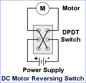
Here is an image of the wiring diagram in the reversing switch, and below is a picture of what the entire wiring diagram looks like:

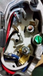
I will also post up some pictures of how the motor connections look like, as well as the wiring diagram that I need comments/corrections on. I'm hoping that all that went wrong was just that initial switch to 115v, and everything else should work fine if I use my current wiring diagram, but I need some reassurance
For about a year now, I have been (off and on) looking for help with wiring a reversing switch to a US Motors general purpose motor. I bought an old South Bend 9" Model A lathe from a gentleman in town and have been in the process of restoring it. I have hit a snag with finding a competent individual in the local area that can wire a reversing switch to my motor. Ive actually already blown through one by erroneously leaving the switches in the back of the motor set up to run on 208v-230v, instead of 115v, which is what I need it to work with
. I know next to nothing myself on electrical systems, but using trial and error, I was able to get the motor to work in both forward and reverse, but after a time, the motor would begin to put out white smoke. I found out that this was from the paraffin wax leaking out of the capacitor on the top of the motor; one of the problems created as a result of the voltage oversight. After leaving it plugged up for a while, the smoke started to turn black in color, so I unplugged it and haven't used it since.Basically what I need help with, is for a savvy member here to take a look at my wiring diagram that I created. This diagram had the motor working properly, but I just wanna make SURE that the wiring is correct before I blow another motor! All I need is for somebody to take a look at it, and offer suggestions, or corrections to the diagram, so I know what I did wrong, as well as offer insight on "whats happening".
I will post pictures of the wiring diagram I need comments/suggestions on, as well as the motor specs, the motor connection diagram and the wiring diagram for the reversing switch. Thank you all!
These are the motor specifics
This illustrates how to set the motor connections. Left side of the diagram is for the 115v, which is what I need it to be set on (115v, single phase, so I can use a regular household plug)
Here is an image of the wiring diagram in the reversing switch, and below is a picture of what the entire wiring diagram looks like:
I will also post up some pictures of how the motor connections look like, as well as the wiring diagram that I need comments/corrections on. I'm hoping that all that went wrong was just that initial switch to 115v, and everything else should work fine if I use my current wiring diagram, but I need some reassurance