Hello,
You got an older motor than I thought. Hehe. Since it is single phase, and there is no capacitor piggy backed on it, I think it is safe to assume it is a split phase motor. In this case, there will be two windings in it: starting and running. The windings are in parallel, but the starting winding is disconnected by a centrifugal switch after the motor reaches 75% of its speed, at which point only the running winding has current going through it. So first thing is first, you have to identify which wire pairs are for which winding. From wikipedia:
https://en.wikipedia.org/wiki/Ac_motor#Split-phase_induction_motor
"A split-phase motor has a startup winding separate from the main winding. When the motor is starting, the startup winding is connected to the power source via a centrifugal switch which is closed at low speed. The starting winding is wound with fewer turns of smaller wire than the main winding, so it has a lower inductance (L) and higher resistance (R)"
Since there are 4 wires coming out of it, and there are 2 coils inside, there are only 2 possible pairs of wires that will have a resistance between them when checking with an Ohm meter. One resistance will be higher than the other. The pair of wires that has a higher resistance will be the starting winding. The pairs of wires that has a lower resistance will be the running winding. Separate the two pairs, and mark the wires so you know which are the ends of which coil.
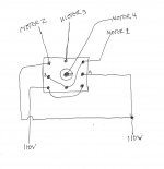
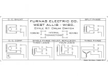
Next, you really have to verify that the switch you have, matches the one in the diagram you provided. There are 6 contacts on the switch, and the diagram shows you which contacts are shorted together in the forward and reverse positions. If you are 100% sure this is accurate, then proceed forward.
This is the combination of internal connections in the switch that seems to be common. Make sure this is what you have, or the wiring will not work right.
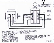
I have a Furnas drum switch as well, and the internal connections are different. Note the difference. This might be what you have too. I don't know.
So, assuming the first style is what you have, you would wire the motor up as shown in the diagram below:
The running winding (lower resistance) is marked with blue letter R, and its wires coming from the motor are connected to the switch terminals colored green.
The starting winding (higher resistance) is marked with red letter S, and its wires coming from the motor are connected to the switch terminals colored purple and yellow.
The 110V power line is coming in from the right. The hot (black wire) is connected to the switch terminal colored black. The neutral (white wire) is connected to the terminal colored white. These could be easily reversed, and functionally it makes no difference which one goes to which terminal, since we are dealing with AC current. So the neutral could go to the black dot, and the hot could go to the white dot. The difference between neutral and hot is that the neutral is the center tap of the transformer on the pole outside your house, and it's tied to ground. Normally, when you are wiring a switch for a lamp in the house, you are "supposed" to switch the hot wire, while the neutral wire is always connected to one end of the light bulb. Ideally, both the neutral and hot could be switched at the same time, but it's cheaper to just use a single switch for wiring a lamp. Since you are dealing with a motor and a drum switch, this consideration could be irrelevant. You might want to look at what the internal connections are inside the drum switch when it is in the off position. If there are no connections at all in the drum switch when it is set to off, then which way the hot and neutral are wired makes no difference.
Now examine how the Neutral and Hot wires are connected through the switch to each of the motor coils.
The running coil is connected to Neutral and Hot in the same exact way for both the forward and reverse positions of the switch.
Now the starting coil is a different story. In the forward position, the purple end of the starting coil goes to Hot, and yellow end goes to Neutral. In the reverse position, the purple end goes to Neutral, and the yellow end goes to Hot.
So..............
When you connect the wires from the running coil to the switch, which end goes where doesn't matter, Pick one orientation and stick with it.
When you connect the wires from the starting coil, pick one orientation, and try it. If you set the switch to forward, and your lathe is running as it should, then you are done. If however, your lathe is running backward with the switch set to forward, then simply reverse the wires from the starting coil inside the switch, and that should fix it.
In theory.

Hopefully this helps, but I make no guarantees. Proceed at your own risk. If anyone out there wants to add or correct anything, please do.
Best of luck.