What's new
What's new

How to fix worn pinion bore in apron?

Doan

Plastic
Joined
Aug 10, 2021
This is for a Heavy 10L, but might be the same for all aprons.
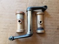
I dug into the carriage to clean an adjust and found the rack pinion gear teeth badly worn. The cast iron bore in the apron is also badly worn. All the felt wicking was long gone. Fortunately the rack teeth seem OK.

The pinion shaft has approx 0.015" play in the apron casting. I can think of a few possible repair strategies - each with a downside.
Installing bushings would cause the loss of the felt keyway.
Plating and grinding the pinion shaft oversize would be expensive.
Making an oversize pinion shaft and somehow installing a gear - expensive or beyond my abilities.
What is the accepted repair?

Also, used South Bend pinion gears are sometimes available on line. Are the 14 tooth pinion gears the same for all the heavy 10-16" lathes? They have different part numbers (PT204R1, PT204T1, PT204F1, PT204H1).

My pinion gear is labeled P10, which means it is Plus 10 thousandths od - correct? Anyone have a replacement?

PinionGear.jpg

Thanks for you help and ideas,
Shawn
 
The gear maybe worn but it is not that bad. Will probablyu last your lifetime and then some. There are a number of repairs that can be done to tighten up this shaft in the bore. You can bush the bore. The pinion shaft will be worn so machining it straight but undersize will be ok if you bush it to size the shaft. You can ream the bore straight but oversize and then build up the shaft with a sleeve and machine to size. You can also braze the shaft and machine to a new bore size. Options are plentiful and most require a little of you time and little expense. An easy fix is to cut gear off to graft to new shaft that is fit to a reamed bore. Changing the shaft allows you to fit the handle tight against the apron for a factory fit. I am sure many will have other options.
 
Thanks for the ideas Tommy. The pinion teeth look terrible to me, sharp and pitted and smeared, but the rack teeth seem OK.

Emanuel, I was wondering if that was standard procedure. :) The handwheel has about 1/8 turn slop and about half seems to be the slop in the bore - and the end of the felt leaks a little oil. (a nice indicator it is working!)
So did all the different size lathes - 10", 13" 14.5" etc. all have different teeth on the pinion and rack? Wouldn't they be standardized on the same tooth form so racks were interchangeable and pinion production all had the same gear cutting setup?
Just wondering...
 
The .015" on shaft oil clearance bothers me less than wear on teeth. Everything in the apron turns at a low rpm especially that gear and shaft, its fastest speed will be when you run handwheel to move saddle up and down ways. So a little slop won't be terrible.

That gear mates with rack under bed. To remove some slop from handwheel and that gear teeth, you can shim rack straight down. You want a little clearance, but you can remove quite a bit of that slop. To figure out how much to shim, loosen rack and slip some feeler gauges in and tighten it back up.

Because you can shim rack down, you don't necessarily need a P10. I'd find any that fits you size lathe, but has perfect teeth. Besides ebay, email Ted aka SBLatheman:

[email protected]
 
Last edited:
Another option to deal with shaft clearance. Bore hole in apron housing and add a bronze bushing. Don't worry about a felt.

Instead drill a passage from the outside to put a gits oiler. I drilled this passage on 2 lathes, though did not need to add bushings. I just wanted to be able to more easily lube high shaft positions that tend to get less oil, you can see drilled passages here:

Getting Another South Bend 16x6 Operational
 
Sometimes putting a thin washer between the handle and the casting can take out a lot of slop without having to bush the bore. Worked for me on a couple of lathes
 
Thanks guys - good write up at that link Tex. the rack already has a stack of shims under it. With a better pinion I might have to remove some! ;)
 
Thanks guys - good write up at that link Tex. the rack already has a stack of shims under it. With a better pinion I might have to remove some! ;)

If the bed was ever re-ground, then the qcgb, rack, and end bearing might have been shimmed down.

When putting it all together I'd check alignment of lead screw though the worm gear in apron. A little tricky, but try to get an eyeball down leadscrew to see if you are centered through worm gear. Also running apron/saddle assembly up and down ways to see how nice movement is, or if it has drag. Another way is to roll qcgb from left end of lathe's gear train. It should spin by hand, if its tight or bindy might need work the alignment a bit. Crack the bolts loose on qcgb and end bearing, but leave pulled up just snug while you work it out.


Thanks for this. It seems smooth and quiet under power, but I will check this way in the morning. Great info!
 
The .015" on shaft oil clearance bothers me less than wear on teeth. Everything in the apron turns at a low rpm especially that gear and shaft, its fastest speed will be when you run handwheel to move saddle up and down ways. So little slop won't be terrible.

That gear mates with rack under bed. To remove some slop from handwheel and that gear teeth, you can shim rack straight down. You want a little clearance, but you can remove quite a bit of that slop. To figure out how much to shim, loosen rack and slip some feeler gauges in and tighten it back up.

Because you can shim rack down, you don't necessarily need a P10. I'd find any that fits you size lathe, but has perfect teeth. Besides ebay, email Ted aka SBLatheman:

[email protected]

its not a 10EE when i first started in the automotive field i was talking to my mentor i was saying how it would be interesting to take a car and balance every thing on the drive train his reply was if you want a Benz then buy one . yes you lathe has a fair amount of play on the hand wheel maybe not as much as when it was new but even when it was new it still had a fair amount and as far as bushing the shaft bore . why not so it has a slot for the wick . if one wanted to they could turn the shaft down if its worn and make a bushing but then you would have to sleeve the handle if there's wear in the pinon shaft and you would have to lok tite the bushing in and cut [ slot ] it for the wick or do all that and leave the pinon shaft alone and if you think the sleeve is going to spin or move you could pin it or just make a small short bushing at the handle end to support it and stop the wobble and that could be done more than one way so you can live with it or fix it by repair or replace but i understand when you grab something that spine you don't want it coming at you even if it just a bit
 
That is very cool John. Interestingly that split bronze bushing is the same design as the rocker bushings on a 1930s Guzzi OHV engine. They are problematic because only 1 half is bolted into the rocker box. The other half, which gets the load as the valve compresses, just floats between the aluminum cap of the rocker box and the bolted half. As it wears, the floating half squirms into and erodes the aluminum cap. It's probably made worse because the bushing and rocker box are split on the same plane.
20210628_132146.jpg20210628_132201.jpg
One solution has been to bore the rocker box and make over sized bushings and I wondered how that was done - and you've done it!
Thanks!
 
That is very cool John. Interestingly that split bronze bushing is the same design as the rocker bushings on a 1930s Guzzi OHV engine. They are problematic because only 1 half is bolted into the rocker box. The other half, which gets the load as the valve compresses, just floats between the aluminum cap of the rocker box and the bolted half. As it wears, the floating half squirms into and erodes the aluminum cap. It's probably made worse because the bushing and rocker box are split on the same plane.
View attachment 327895View attachment 327896
One solution has been to bore the rocker box and make over sized bushings and I wondered how that was done - and you've done it!
Thanks!

that's right up there with the after market OHV model T head a guy showed me 40 something years ago that instead of a rocker arm had a harden curved tube full of ball bearings
 
Late to the party but this was my approach:

1) cut the pinion gear off the worn shaft.
2) fabricate an oversize shaft.
3) bore the existing pinion and silver-solder it to the new shaft.
4) new shaft will be the same dia as the old one where the handwheel pins on.
5) bore the apron to correct the offset downwards if it's bad, and ream to size. Otherwise juts ream up to the new size.

Often its easier to make the shaft to fit the new bore so you do the apron job first.
 
that's right up there with the after market OHV model T head a guy showed me 40 something years ago that instead of a rocker arm had a harden curved tube full of ball bearings

How did that work? Were the bearings just to keep the tube from collapsing?

Thanks for your ideas too!
 
Thanks Jim, this is the direction I'm leaning. The handwheel is not on the same shaft, but an intermediate gear is, so that would need to get reamed over size too.
 
Thanks Jim, this is the direction I'm leaning. The handwheel is not on the same shaft, but an intermediate gear is so that would need to get reamed over size too.


Hmm. This was an old single-tumbler 10L so I guess the floppy handwheel fix and the pinion gear shaft fix happened at the same time. Distinctly recall cutting the pinion off and boring it out and fitting to a new shaft.
 
How did that work? Were the bearings just to keep the tube from collapsing?

Thanks for your ideas too!

the ball bearings were moving inside the tube . the tube had a 180 deg. bend . so the push rod was at one end of the fixed tube pushing the balls in as the push rod went up and the balls at the other end would push out and open the valve . there must have been some plungers at each end between the balls and valve and the push rod never seen the complete assy. and it was over 40 years ago


Back
Top