Hi all,
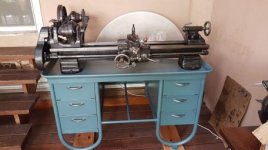
My father and I are restoring a 1965 Workshop model B lathe.
We hastily took everything apart, painted it, and are in the final stages of putting it all back together.
However, there is something really weird with the countershaft alignment.
The lathe is horizontally driven, and all is bolted down to an original tubular steel bench.
The problem is, using the original holes in the bench, we can't move the countershaft left enough, so the pulleys can't align and the belt slips.
First we mounted the headstock so the stud gear will align with the gear on the banjo.
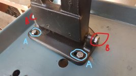
Then we moved the countershaft as left as possible on the bench (bolts A in the picture), and screwed the mounting screws (B in the picture) to the left as well. the pulley on the shaft is also positioned left as possible.
We are still about 5/8 inch short.
I've been searching for errors in the reassembly but couldn't find any.
Do you have any idea what is causing this misalignment? We are truly clueless.
Thanks in advance,
Maor
My father and I are restoring a 1965 Workshop model B lathe.
We hastily took everything apart, painted it, and are in the final stages of putting it all back together.
However, there is something really weird with the countershaft alignment.
The lathe is horizontally driven, and all is bolted down to an original tubular steel bench.
The problem is, using the original holes in the bench, we can't move the countershaft left enough, so the pulleys can't align and the belt slips.
First we mounted the headstock so the stud gear will align with the gear on the banjo.
Then we moved the countershaft as left as possible on the bench (bolts A in the picture), and screwed the mounting screws (B in the picture) to the left as well. the pulley on the shaft is also positioned left as possible.
We are still about 5/8 inch short.
I've been searching for errors in the reassembly but couldn't find any.
Do you have any idea what is causing this misalignment? We are truly clueless.
Thanks in advance,
Maor


")