What's new
What's new

Large Dial Conversion 16" Lathe (Cross Feed)

Kevin T

Stainless
Joined
Jan 26, 2019
I have been collecting parts to do a swap to a large dial on my cross feed and thought I was all set when I saw a 14 1/2 large dial for sale on ebay recently. After checking my books I thought I was in the clear to use it since the parts I got were the same for a 14 1/2 and a 16 but not so fast!
P1070339.jpg

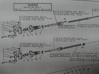
The assembly I got was from a non-taper attachment equipped machine and mine has the taper attachment so I knew there would be some differences but I missed that my detail #11,12,13 was going to end up being too short with the thicker large dials and extended #20 on there (from the above diagram).

It looks like I "may" be able to make an extension sleeve and integrate detail #18 into the sleeve so that it's stronger but I'm in a place I didn't expect so it's best to see what you guys know or have done if you encountered this before.

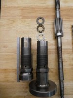
The old and new detail #20
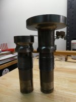
image0004.jpg

The array of parts I have acquired. I have a diameter reading and a radius dial, and two thrust bearing and washer sets from the newly acquired 14 1/2 non taper attached lathe.

image0002.jpg


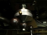
Here you can see where I fall short considering I need room for my crank handle!

image0009.jpg

image0010.jpg

no room!!!

Are there any words of wisdom or pointers to get the rest of the way? Thanks. It looks like part #11,12,13 is different lengths between a standard dial and large dial but I don't seem to have that documentation. I'm pretty sure I could make a threaded extension but before I do I want to see what you guys say (or maybe have done if you encountered this)

Cheers
 
Short answer: Chop off the dial portion of shaft from the engine lathe CF screw you have and don't need, maybe cut it close to gear. Chop off a couple of inches from your two piece taper attachment type as well. Now center drill the taper attachment type, to maybe 75% of the diameter of shaft. Turn down the end of engine lathe type to fit hole in taper attachment type. Press the two together to gain length. Either loctite the two pieces when pressed, or cross drill a pin.

Caveat: If engine lathe CF screw has little or no wear on feed threads, sell it, and buy a worn out one cheap to do the same.

I have a similar issue, but I dont need more length. I was setting up for a taper attachment on my 2H lathe. Bought a new dial side portion of CF, two piece type. Not South Bend new, but new from a guy making them. Problem is his gear teeth are a bad match. Once installed, it made noise and felt terrible, regardless of how I tried to set gear lash.

You can see the difference in gear teeth. The one of left is original South Bend:

358.jpg

Long story short, I bought a used, but known damaged one from Ted, full disclosure, I knew on purchase. The used one is damaged on threaded nut end, and bent on first step below threads.

When I get around to it, I'm going to chop both somewhere in the vicinity the screw driver is pointing.

359.jpg

I'll center drill the original South Bend used one. Cut the shaft of new one longer. Turn down the end to get pressed in. And press them together.
 
..."Short answer: Chop off the dial portion of shaft from the engine lathe CF screw you have and don't need, maybe cut it close to gear. Chop off a couple of inches from your two piece taper attachment type as well. Now center drill the taper attachment type, to maybe 75% of the diameter of shaft. Turn down the end of engine lathe type to fit hole in taper attachment type. Press the two together to gain length. Either loctite the two pieces when pressed, or cross drill a pin."...

Thanks for the idea. I was trying to avoid taking my saddle apart. You may have thought my saddle was apart because of the extra screw in my photo but I have a spare. Also the new CF screw shows no wear at all so it's a cherry part that should fetch some bucks that I need. Having it here though is good for me to take measurements off of.
 
Here is a little more. The new part for a non taper equipped lathe has a thrust washer setup between the detail and the gear on the CF shaft. I don't think it is needed in mine? I lined these two up on the mating line when they are screwed in to the saddle

image01.jpg
 
Thanks for the idea. I was trying to avoid taking my saddle apart. You may have thought my saddle was apart because of the extra screw in my photo but I have a spare. Also the new CF screw shows no wear at all so it's a cherry part that should fetch some bucks that I need. Having it here though is good for me to take measurements off of.

There is good news if it comes to it. An engine lathe CF screw is trapped once apron is up. That's due to the cut of gear teeth, with un-finished cut of gear teeth between apron gear and dial. You need to raise saddle or drop apron to remove that style CF screw.

With a two piece style for taper attachment, you do not. The un-finished portion of gear cut is between apron gear and taper attachment. Saddle and apron can remain on bed to remove it.

You can also remove the long portion of CF screw without dropping taper attachment, if the slider that lead screw passes through is cleaned and lubed. Just knock the taper pin out below the tightening handle on taper attachment. If the lathe is close to a wall, that might be tough.

Another option to increasing length. Just cut the shaft on your current two piece style, and and add your own extension from bought material.
 
Here is a little more. The new part for a non taper equipped lathe has a thrust washer setup between the detail and the gear on the CF shaft. I don't think it is needed in mine? I lined these two up on the mating line when they are screwed in to the saddle

View attachment 317540

There are different styles and lengths. Your original, being from 1942-43, did not have thrust bearings on both sides of dial bushing. Maybe some others did. In general an engine lathe will take those thrust bearings. Because they do see thrust.

Your two piece, for taper attachment, the long portion running through taper attachment feels the hard thrust of tool post being pulled into work, while the dial side does not. Dial side just floats because of the slip joint. Taper attachment side is held fast plus pulls the CF nut of compound.

So strictly speaking you dont need it. But having it wont hurt maybe. One important factor is where gear teeth ride in conjunction with apron gear.

And its a great big stupid South Bend trick ! :D The gear teeth look super wide on CF. Can put anywhere right ? HA
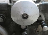
I guarantee your current, original two piece, that the dial side section is running on the gear teeth very close to the unfinish section of gear teeth cut. In essence, attempting to move that portion of crossfeed even a 1/4" more toward dial will cause un-finished teeth to be wedged on apron gear. While pushing that section toward taper attachment you have maybe 1/2" before the slip joint would bottom out if using taper attachment to cut an actual taper to its furthest allowable degree point.

Real point being, when you really sit down to do it. Get all your pieces where you can physically check operation of T/A, gear mesh, lengths etc.

Edit:
You can just barely see the shadow on gear teeth of wear for where this rides on apron gear. Pic may look deceiving, but you have about 1/8" before you'd feel it binding on apron gear, if moving toward un-finished gear tooth cut. Real close to un-finished gear cut:

127.jpg
 
Here is a little more. The new part for a non taper equipped lathe has a thrust washer setup between the detail and the gear on the CF shaft. I don't think it is needed in mine? I lined these two up on the mating line when they are screwed in to the saddle

View attachment 317540

Just re-looking your pic. With what I assume is original style to your set up on left, being internally longer. An eyeball estimate of new bushing, I think using that thrust bearing would keep your gear in real close to original location, depth wise.

Doesn't solve the too short shaft problem, but keeping that gear and slip joint in operational range is a plus.

Yes thanks, actually it's pretty close to the correct insertion depth if I use the thrust washer/bearing/washer setup. So I am thinking I will use it. If I am a few "tens" off I am thinking that is OK. Or are you saying that because of that wear mark on your gear I need to be really close?

I'm running a repop CF screw that Naru cut for me and his keyway grooves were a little longer than stock too so I may be fine no matter what I do but you got me thinking.

I am leaning toward an extension for the missing length that incorporates that detail #18 from my diagram above. I think I can manage to make it although it would be a stretch goal for me to assume I could nail it the first time! LOL

In this vain I re-installed the old detail #20 to see how far the short shaft sticks out with handle installed and I am planning to measure this and plan a design for an extension detail. In my mind this way I haven't really messed up any parts and I still have a lot of options if it fails.

Of course I expect to see Ted pop in here and tell me that he has just the part I need for $$$!!! I just never know when he will show up. After I spend 10 hours making a bad part or before! lol

Do you see anything wrong with this plan?
 
Your insertion depth can be 1/16" off with no consequence, maybe as much as 1/8". More than that could be a problem. And looking again at the stack side by side pic (must of missed that :D ), I think that portion is fine.

I would have bought a good one from Ted if he had it, but his pickings for taper attachment types were thin. Though again, I was looking for short shafts, as my large dial is not extended.

Another potential thought for you. I had my head wrapped around getting shaft extended out far enough for retaining nut. Does not really need to be does it ? Could possibly chop threads and first step off the shaft. Instead of extending, drill and tap a hole into the remaining shaft. Then make a shouldered bolt to pass through handle and outer dial.

Could even pretty up the bolt. Rounded, with two drill holes in outer surface, use a pin spanner to tighten it. Bolt is shouldered to tighten to remaining shaft, but not tight outer dial.

Probably have to drill and pin handle prior to tightening bolt though. Handle could then help you tighten bolt.
 
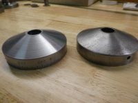
Soooo...moving right along. I'm cleaning up what I have for the eventual swap to large dial. I did get a beat up Direct Reading dial that was abused but just cleaned it up.

image0001.jpg

These are big gouges in the face and not nice to look at so I did some compound hand feed gymnastics to clean up that face (in my new to me 4 jaw chuck). It's about a 21.75 degree angle in case you were wondering.lol

It must be from a newer era because of the satin finish. Man that satin finish makes it easy to see the numbers!

image03.jpg

I also have a Standard Graduated collar that is probably from closer to the era of my lathe.

image04.jpg

Since I have a choice which one to run does anyone have any comments about which one you like and why?

image05.jpg

I like the standard one with 125 graduations because it looks more correct for my lathe but I'm getting old and that satin finish really helps me see the #'s
 
The older I get, the more I like really good light. Soon you'll see my shop from outer space. :D

I also really like good, easy to see visuals. It could be a fallacy, but I feel I'm more accurate with direct readings.
 
Last edited:
Well that was a good part of my Sunday! I removed the taper attachment by replacing the two attach bolts with some foot long threaded rod so I could slide the assy back far enough to clear the feed screw. It was pretty easy after that but it took me a while to figure it out.

image11.jpg

Still not ready for prime time I need to make a small pin to hold the dial when I tighten the lock nut for reading and there's some slop between the handle and the graduated collar to the tune of about .024. I have some arbor shims inbound to fix that.

Also the extended collar does not have a zero indicator line scribed on it. Were they added by the installer?
 
Were they added by the installer?

Yes, never know where your entry thread started in compound, or the same for bushing. Plus each person might tighten a little harder than the other guy.

If you're tight on that bushing, and set with all else. Then mark 12' oclock. Remove and scribe it. I did the shaper trick, using lathe un-powered. Put bushing in chuck with the 12 oclock mark now at lathe tool centerline, lock spindle. Using a very sharpe pointed lathe tool, I ran saddle back and forth by hand. Fed crossfeed in till I kissed, and just fed in till the scribed line looked nice and visible.

If you are worried, practice at the 6 oclock position first, noone will see it. :D
 
Why not simply make a new custom dial and attach it to the face of the old (smaller) dial, outboard ?

FWIW my Sheldon r-15 has very nice large dials, I don't see why you couldn't make similar as an add on, retaining all the features with the small dial.
 
Yes, never know where your entry thread started in compound, or the same for bushing. Plus each person might tighten a little harder than the other guy.

If you're tight on that bushing, and set with all else. Then mark 12' oclock. Remove and scribe it. I did the shaper trick, using lathe un-powered. Put bushing in chuck with the 12 oclock mark now at lathe tool centerline, lock spindle. Using a very sharpe pointed lathe tool, I ran saddle back and forth by hand. Fed crossfeed in till I kissed, and just fed in till the scribed line looked nice and visible.

If you are worried, practice at the 6 oclock position first, noone will see it. :D

Cool, the entire assy. looks so unused so the no mark info is great to hear. Do you stamp a zero on it too? My stamp set is too big to use but I was thinking about maybe sacrificing small hole punch to make an "0".
 
Why not simply make a new custom dial and attach it to the face of the old (smaller) dial, outboard ?

FWIW my Sheldon r-15 has very nice large dials, I don't see why you couldn't make similar as an add on, retaining all the features with the small dial.

I thought about trying some of this kind of stuff too. I was looking for old dials for cheap to try but didn't get around to it. There is a good amount of satisfaction too, for me, in using the correct stuff and the shaft I pulled out of my machine had some wear on it and the non gear diameters were a little worn down. When compared to the new part the difference was .02 on the diameters. Funny that the gear splines on the new part are not as nice looking to the eye as my old part but maybe the part wasn't stored ideally over the years. The CF feels much smoother today!

Your idea has a lot of merit if it can be done because with the newparts one must stand farther away from the lathe when over the CF since it sticks out farther and it's something to get in the way that wasn't there before. I'm sure I could bump it since I'm not used to it but hopefully only during oiling! lol
 
Well finally got it converted and I'm happy with the result. I had a sort of big screwup that I resolved that might help someone in the future. I over engraved my Zero line on my precious part. Word to the wise, all you need is the faintest of scratches to work with because if you go to deep...whoops. I went to deep with mine which was going to make lining up on those .000001 cuts difficult for these old eyes,but wait... I used a piece of guitar string in the oversized groove and it's an improvement! whew that was close!

dial0001.jpg

dial0009.jpg
 
I had a pre-etched assembly for one lathe, going to another. Naturally the bushing didn't tighten into saddle with mark at 12 oclock. But I could use shims to adjust where it tightened. Also putting bushing in chuck, I could cut mating face a bit to change orientation.

I mention in case you want to have a do-over. Could potentially move current mark to 6 oclock. Try something new at new 12 oclock.

I think it looks fine btw. And being direct read now your eye ball use of dial will better gauge how much on or over dial line to indicator should be. At least it feels that way for me.

NO DO OVER!!!! lol

It looks really, really good to my eye like this. Like a good scope reticle.....I'm done with this project! Like I said I got lucky...this time!


Back
Top