FrankW
Plastic
- Joined
- Mar 18, 2007
- Location
- Johns Island
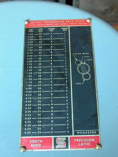
Can anyone point me to information on metric transposing gears for a SB 13" lathe?
I have a couple of SB 13's and would like to setup one to do metric threading.
I searched the normal forums and did not find anything for the SB 13.
Either a source for the gears and threading charts such as those available for the SB 10 or the specifications for the gears so we can cut them in our shop.
Thanks,
Frank