What's new
What's new

Operational considerations of compound rest

texasgeartrain

Titanium
Joined
Feb 23, 2016
Location
Houston, TX
I have what may seem like random, or all over the place questions or thoughts in relation to tool post placement and compound rest use and general location placement of it. But I'm working toward what I hope is the best overall positioning and use of the combination.

And I do understand, that to certain degree, its a loaded question, or tough to answer, as there are nearly endless set ups, ways of doing things, or varying work specific circumstances.

But in very basic or general terms some questions I have:

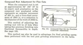
1. Are you guys generally setting compound rest to 84 degrees, I presume to better sneak up on work and get finer results in sub .001" range ?

2. If so, are you aligning tool post 90 degress to work ?

3. Are you generally biasing your tool post to one side or the other on the rest, or planting it in the middle? And are you using full length tee nuts to edge of tee slot to reduce chip gathering places ?

4. Generally, do you keep tool post side, of the upper portion of compound rest, right on the edge of the intermediate section ? For cleanliness, to reduce chips on that dovetail ?

5. Do you find you drive the rest back and forth its full range ? Or are you operating in a small range ? If you're using the full range, what's the common circumstance ?

I probably have more, but i didn't write it down, now its flown away, lol.
 
Not in any real order here, but here goes a couple of my answers anyway:

If I have to work less than a thou: have a dead sharp HSS tool. Leave everything where it was on the last pass, but set up the finest feed I got. As it goes into the cut, I actually put my hand on the toolpost and lean on it like a tired man leaning on a fencepost. Good for a few tenths that way. I actually practiced this to see how much I could vary it. Give it a try!

Working to tenths, I would rather use the file and emery paper though.

Sometimes I use the full range on the compound rest. Especially if I'm cutting a taper or say a 60 degrees point with the tool on the backside and running the lathe in reverse.... gives me the room to do the job without running my hand into the chuck on the front side.

Otherwise most of the time I try to leave the compound "centered" so it has lots of support.

99% of the time I have the compound at 30 degrees (29.5ish) and keep the tool square to the work, or keep the tool parallel to the face of the chuck.
 
1. Mine has been set to 29.5 for a while since I am messing about with threads.
2. Yup
3. I am usually avoiding the obstacles
4. ?
5. If you are using it to creep up on a number then not a lot of range yeah?
 

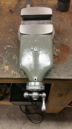
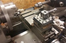
Note the upper compound rest in both pics. One leaves dovetail exposed.

Not just lathes, could be a mill or anything, but many such dovetails, right in the middle of the action like that, might have wipers or shields. These do not, not originally anyway.

Was curious if all things being equal, do people generally run with rest moved forward to cover dovetail.

Pavt's leaving it centered for support falls into line with my guess. Just fishing for more info, haha.

224.jpg 225.jpg
 
Here is a table that I created to set the desired feed on the compound. I was boring a hole to 0.2502", so I had to get a little more precision in the feeds. This is in an Excel spreadsheet, so it doesn't transfer that easily to an image.

attachment.php


I usually keep the "too lpost" as fully on the compound as can be.

I always keep as much iron under the cut as possible.
 
I have not got into threading yet. I'm sure that will change at some point, I'm just not there yet. Considering that, I like the 84 degree plan, where .001" on rest dial should translate into .0001". Nice and simple, and less I need to think.

To help with that, I'm going to use a large, 200 increment dial on the rest for my 2H lathe. That legit, will translate into .0001" in work, cutting down math I need run in my head, instead of doubling the number for a 100 increment dial.

242.jpg 243.jpg

Since I'm leaning my basic general set up at 84 degrees. I was thinking I will bias my tool post to one side of rest, going away from work, to buy a little more swing:

240.jpg 241.jpg
 
To reduce chips on dovetail, I was thinking leaving top edge exposed a little will be easier to brush off:

244.jpg

This could also work, but I think it would be more difficult to clean:

245.jpg

Going in those general directions, would put tool post about an inch bias toward headstock, when looking down saddle dove tail:

246.jpg

To compensate, I am thinking to make my own full length tee nut, but drill hole closer to one edge, instead of center. That will bring tool post closer to saddle dovetail center:

247.jpg
 
I have had my 10L for 45 years now. The last 30 years I have made many 5 Gal pails of chips, sometimes 1 a week.

I use a large 100 division dial on the compound, and a large 200 division on the cross slide.

I keep the compound at 90 degrees (parallel with the bed).
For many small operations, I lock the carriage and use the compound for the Z axis, like a speed lathe.
This is the only way to pick up mangled threads that need to be cleaned up!
The tool post is positioned so I can face and turn with my 80 degree Trigon tool, and cut off a part using a cutoff tool.

I don't use a DRO or Travel dial (in the way too much)

I use a full length T nut with the hole centered, this keeps the bottom of the Aloris dovetails open to let chips fall clear VS packing up under the sliding wedge. See your last pix.

I normally try to keep the compound 1/4" from full extension. The tool block helps to keep the chips off the compound dovetail.
The 1/4" of travel is large enough for many small operations, I normally take the compound back to 0 at the completion of the operation ready for the next part.

Early on I tried the 84 degree thing. I found that trying to dust off a few tenths was a pain, Eventually I changed to filing and working with India stones soaked in mineral spirits for tight dimensions and fine finishes. It's a LATHE, and not a GRINDER ya know!!!

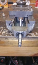
Looking at your last pix, I would cut the end of your screw off square and Loctite it into the nut, so a little heat will free it up for fitting into the second or third trial nut.

'nuff for now,
Bill
 
Looking at your last pix, I would cut the end of your screw off square and Loctite it into the nut, so a little heat will free it up for fitting into the second or third trial nut.

'nuff for now,
Bill

Good Stuff, I appreciate it.

In the last pic, the bolt is up side down. I just shoved it in for reference.
 
Maybe I can explain a few of the reasons why removing a 10th or two with any lathe is a whole lot tougher than it looks and is going to require a fair amount of skill, knowledge, a machine "properly" installed & adjusted, as well as being in extremely good condition Plus a hell of a good job done while choosing the correct angles for the material type, sharpening and honeing the tool. Despite what the theory says that feed advancement should be with an angled top slide it's still only theory. Taking a 10th off isn't impossible, but everything above and more has to be correct first. George Thomas's book The Model Engineers Workshop Manual goes into some detail about that proper slide adjustment and also mentions far too many have there top slides adjusted much too tight for reliable movement against what the dial says it's moved.If what I see on Youtube are averages of what most are doing in there own shops then I'd say George was pretty much correct. Many forum posters even mention that they keep there top slides tight. Maybe that helps with a seriously worn machine, but it greatly accelerates feed screw, nut and dovetail wear. George recommended adjusting the top slides gib with the feed screw removed and the top slide should traverse back and forth along the length of the dovetail with just light finger pressure and with an easy silky smooth movement with no trace of shake or tightness at any point. For lathe top slides with set screw adjustable gibs he also details how to pin it in place to prevent the gib moving longitudinally and tightening that finely set adjustment as it slides very slightly up the points of the gib screws due to friction from the dovetail wall as the top slide is moved in either direction.A variably worn set of dovetails,too tight adjustment, highly worn feed screw / nut and maybe last cleaned sometime back in the late 20th century, poor or incorrect lubrication, non pinned gib etc, etc just ain't going to do it. That too tight adjustment and the unavoidable clearances between all the parts that allow it to even move creates problems with the forces building up until they over come the frictional forces and then the slide advances much less or much more than your expecting.

The higher your accuracy expectations are then the more knowledge, skill, time, expense, and effort it's going to take throughout the whole machine to match what your asking it to do. Yes fairly high accuracy and parallel parts can still be produced on somewhat worn lathe bed ways because changes along the bed due to that wear have very little effect since the tool point is moving vertically on the parts radius. The larger the parts diameter the less measurable change in diameter that vertical movement has. A very slightly twisted bed is completely different. Because of the vertical distance between the bed ways and the tool point it greatly amplifies any bed twist effect. Visualize it as it slowly rolling the tool point either into or away from the part as the carriage traverses along the lathe bed and that's what causes that taper. Trying for a single 10ths material removal on the part diameter takes at least 50 millionths repeatability from the machine.What condition and how well adjusted and aligned is the rest of the lathe? Head stock bearing type and adjustment? What's your shop floor made of and how rigid is the lathe bench? If it always cuts a .001" taper over 3" while trying for that 10ths removal then it's rather pointless since the rest of the machine isn't up to what your expecting. Even being certain of your measurements at that 10ths level isn't at all easy or cheap. Multiply that about 10 times for any internal measurements. I've spent almost 40 years learning as much as I could and the little I'd now like to think I know about machining, metrology,machine tool rebuilding and alignment, tool sharpening etc I still wouldn't bet real money I could hit those 10ths numbers even twice out of 10 try's at it on a light weight home shop sized lathe. That angled top slide method is only a mathematical proven concept for what the machine should do. It doesn't factor in the rest of the machine, the operators skills or any of the variables and unavoidable realities.

As Bill already pointed out it's a lathe not a grinder.So if repeatable 10ths level accuracy is really required and it's paying well enough then at the bare minimum a decent tool post grinder and the skill and experience to select the correct wheels and use it well would make it a bit easier. That and hardened parts are why they were invented.Using one still isn't a replacement for a much better and proper radial type grinding machine, but that would be out of the question for most of us.

If I was really concerned about chips contaminating any dovetail I'd add some decent rubber or plastic wipers and oil felts behind those. Any high end lathe is already designed and comes from the factory with something like that already in place.There's at least a couple of aftermarket supplier websites where ideas can be borrowed / stolen from.For some reason setting the top slide parallel to the lathes longitudinal travel seems to be mostly a British and rest of Europe habit although some in NA will also do so plus as it's been already mentioned there's no other way with those speed type lathes that don't have a real carriage and feed rod or lead screw. I don't see anything much to gain from it for the more usual types of lathes other than possibly avoiding the effects of bed twist from a poorly installed machine. That position can also cause interference problems between it and the tail stock when turning with live or dead center support. With a good condition well made lathe correctly installed,leveled and adjusted the bed ways are already aligned parallel and square to the head stocks C/L. Top slide parallel turning does on most lathes have a dial for the distance traveled. Many lathes have no direct means of indicating the carriage travel but that's not a real obstacle since a standard 1" travel indicator, micrometer setting rods or gauge blocks can be used from .000" - whatever length of extra rods or gauge blocks you have and the part dimensions need. And for chambering any rifle barrels I'd want to be using something like it as well as the proper go/no go gauges.For myself I generally keep my top slide at 29 - 29.5 degrees for single pointing threads. That way it's already pre set and most times is out of the way of the tail stock and dead / live center. At some point I plan on adding a proper cast iron riser block for my lathes tool post and completely removing the top slide except for shorter tapers or screw cutting use. For anyone interested enough both Stefan Gotteswinter and Robinbrenze have made extremely logical videos on YT and there reasoning behind and the real benefits of doing so. I sure don't expect to change anyone's mind with this, but George Thomas also made good logical sense about his preferred choice of using the standard 4 position turett type tool post over any of the American, British or European quick change tool posts due to the much better tool support, rigidity and far less deflection they have over any of the quick change designs. If anyone disbelieves the built in issues with any QC tool post just set a magnetic base in the chip pan and the indicator tip on the tool post in Y or Z as the tool starts even a .010" depth of cut.If I was really trying to remove that 10th I'd use my lathes OEM turett over the QC tool post.For most of us with a home shop those quick change tool posts and holders are probably more of a convenience than an absolute necessity if your wanting the very best out of your lathe. And yes I do own and most times will use a couple of sizes of them because I'm also lazy. :-)
 
Lots and lots of writing. . .

Funny coincidence on some of the things mentioned. As I have been going through some it. First the idea of removing your rest for just a tool post. . . That's my basic set up now. Simple and very rigid. I have been reluctant to give it up actually, as most of the work I have done has been more basic.

261.jpg

Also, like you mentioned on setting gibs first. I literally was just going through that this week. I set the gib without dial in, so screw would not affect the resistance. And it was really nice.

But getting alignment of screw correct enough to have really nice and clean travel was a nightmare. Even now, its not perfect, but I'll call it 80% clean and nice travel.

227.jpg 262.jpg 263.jpg 264.jpg
 
So my recent threading woes got my attention today as I was practicing with a 3/4-10 thread. i watched my compound crank handle flop back down on me during operation in the middle of cutting a thread! Looks like my setup has some serious slop in the assy. I think I need to shim between the feedscrew and the rest bushing .019! Have any of you guys had to do this? What are my options? I am eyeing a couple large dials on ebay but it's just the graduated dial so I would have to make the rest bushing. Making stuff like that is why I am practicing threads but my results are not great so far...no wonder with a free wheeling handle! LOL

How do I tell if a large graduated collar is a Standard, Direct Reading or Metric? My need is for a 16" compound rest.

I have pics that I will posting in another thread soon on this. But basically the thrust in and out of compound rest right ?

That thrust is controlled by 2 walls. the .019" thrust on yours, is what bounces between those two walls.

One wall is the thrust collar on screw, which pushes against the threaded, internal portion of dial, it screws into the actual rest housing...

The other wall is the little hand wheel that you use to crank. Part of the base of that hand wheel should bottom out on one step of little fead screw. The other part of its small base provides a little room for thrust on free spinning portion of dial.

So I would first check that the little hand crank is bottoming out on inner step.

If so, you have a few options. One cut that step lower (harder to do without possible thread damage to screw). Or shim between dial and hand wheel. Or shim between the two dial pieces. Or, like you said, shim between screw and bushing.

A temporary fix: Loosen thumb screw for setting dial to zero. Turn hand wheel, so that screw thrusts out, while using fingers to push dial forward. Lock thumb screw.

An FYI on your other question. All dials have x amount of graduations/increments based on screw thickness size and threads per inch, or probably just TPI. Its a math equation.

On 16's, the rest feed screw is 1/2-10 right hand. A dial reading radius would be 100 graduations, where you double the math in your head. The larger dials usually read direct (actual amount removed from diameter, don't double the number in your head), so have 200 grads.

In the case of small dial. 10 tpi screw. 100 grad dial equals .100"., .100" x 10 (tpi) = 1"


Back
Top