What's new
What's new

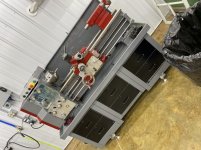
South Bend 13" Build date May10 1988 serial number#000020R1 model number#4229

Mr. Dahms

Plastic
Joined
Mar 6, 2020
I need some help looking for a reasonably detailed diagram of the electrical for this Lathe
more than willing to pay for this document, I have contacted South Bend.com Grizzly.com with no avail.
I'm getting a manual from grizzly but they had stated it does not have any electrical diagram in it.

anyone's help would be greatly appreciative
thank you in advance Mr. Dahms
 
Generally, lathes were set up to customer specs at the factory, or even at a distributor.

This is probably the best it gets:

attachment.php


attachment.php
 
I need some help looking for a reasonably detailed diagram of the electrical for this Lathe
more than willing to pay for this document, I have contacted South Bend.com Grizzly.com with no avail.
I'm getting a manual from grizzly but they had stated it does not have any electrical diagram in it.

anyone's help would be greatly appreciative
thank you in advance Mr. Dahms

That model is a special 1308 built for the military.
I have an original manual for that machine that includes a wiring diagram for sale.
Send me an email if you are interested.
Ted
[email protected]
 
I need some help looking for a reasonably detailed diagram of the electrical for this Lathe
more than willing to pay for this document, I have contacted South Bend.com Grizzly.com with no avail.
I'm getting a manual from grizzly but they had stated it does not have any electrical diagram in it.

anyone's help would be greatly appreciative
thank you in advance Mr. Dahms
I also have one of those lathes and have for 15 yrs. If you have specific questions, just ask.
 
Well I appreciate that offer so here we go,
I need either a detailed drawing or a pictures of your switches on the top of the large control box
The short story is I need to know which wire goes to which switch on and off switch he stop switch jog switch and so on

We help there would be greatly appreciated
Thank you in advance
 
Steve:
I do have a question that may be able help me with,
my taper attachment is missing a part.
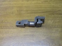
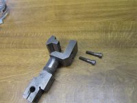
At the end of the rod there is an attachment (A Block) that clamps on to back side of the rail which allows it to actually operate.
If you would have any pictures that you would be willing to share that would be fantastic
in the manual I got from Ted, it's a cross-section DD with part number's
62,61,60,59,58,56,55,54,and 57
thank you in advance

Here you are:
 

Attachments

  • IMG_1692.jpg
    IMG_1692.jpg
    92.9 KB · Views: 62
  • IMG_1693.jpg
    IMG_1693.jpg
    92.8 KB · Views: 62
  • IMG_1696.jpg
    IMG_1696.jpg
    93.6 KB · Views: 62
  • IMG_1694.jpg
    IMG_1694.jpg
    93 KB · Views: 52
  • IMG_1695.jpg
    IMG_1695.jpg
    92.7 KB · Views: 50
Well I appreciate that offer so here we go,
I need either a detailed drawing or a pictures of your switches on the top of the large control box
The short story is I need to know which wire goes to which switch on and off switch he stop switch jog switch and so on

We help there would be greatly appreciated
Thank you in advance

You are correct, there is no wiring diagram available, but it is pretty simple. When I got mine many years ago, it had fallen off a forklift landing on its front face and then on its head completely crushing that box with all the switches. I spent a lot of time with miniature hydraulic jacks and a small porta-power jacking it back straight and replacing all the broken switches and lamps. I also have travel limit switches for the carriage on mine. All of these things are powered by a 24V ac control transformer in the electrical box on the back side of the head stock. These are simple series interlock circuits. Remember if you use a meter to trace this voltage the transformer return is not connected to ground or to the frame, so the voltmeter must be attached to the transformer end. Please note that the relay coils are also 24V.

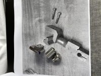
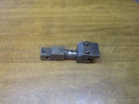
You will note the photographed bed clamp is totally adjustable in both length and angle as well as the attachment rod is articulated. This removes all stresses to the TA to prevent any binding. it is kind of unique.
 
Steve:
after a got the manual from Ted, we got it up and runny.
I will send you a few Pic's
thanks again
 
IMG_9010.jpg
Steve: sorry to here you were in hospital, I hope all is Good!
back to the Lathe, I have attach two pictures started making parts for the Taper attachment
thanks againIMG_8954.jpg
 
Wow, that's a lot cleaner than mine! By the way, this lathe is leveled by adding or removing shims between the bed casting and cabinet. To facilitate that, I drilled and tapped holes in the bed feet for jacking screws. When the bed is measured straight, you just measure the generated space with feeler gauges then build shim packs to match. The jacking screws make the job very easy.
 
Steve:
thank you for the info on leveling out the lathe Bed, My presently is cutting bit of taper will give it a go.

thanks


Back
Top