What's new
What's new

Specifications on South Bend 13" cross feed screw with taper attachment

ctjctj

Plastic
Joined
Mar 11, 2020
I'm in the process of replacing the cross feed screw on my 1947 South Bend 13x5.

I can take the taper attachment off and remove the lead screw and measure everything, then put it all back together, but I was hoping that somebody has a diagram with measurements or something in a CAD program.

Looking on E-bay I see I can just buy one, but I want to do it as a project. I'm going to pick up a replacement nut and cut the threads to match.

Thank you.

Chris
---
1947 South Bend 13x5 560TKR8
1950's Bridgport
 
SOLVED: Drawing of Cross Feed Slide

I took the cross feed lead screw out today and did some measurements. I'm hoping the attached PDF helps somebody else.

NOTES: I didn't measure or mark the key way. I realized that after I had the screw back in the lathe and I don't need the lathe to cut the key way, so I'll take the lead screw out again only when I'm ready to replace it.

I'm self taught and my ability to use Inventor is poor. So the drawing reflects that. Here are some things that are missing from the drawing: There is a lead in taper on the screw side about .375 long. The total lengths were measured to the nearest 1/16th.

From what I can tell the lengths are not critical. The length of the small end needs to be long enough to reach through the TA guide tube. It needs to be short enough so that the 7/16-14 threads can snug everything up to the thrust bearings.

If you have questions about my drawing, feel free to ask.

SB.jpg

Chris
---
1947 South Bend 13x5 560TKR8
1950's Bridgport[/QUOTE]
 
I replaced mine about two -three years ago. I'll try to find where I purchased the threaded shaft. I should have the order here somewhere. Actually bought two rods. Have one as a spare now.
 
I took the cross feed lead screw out today and did some measurements. I'm hoping the attached PDF helps somebody else.

NOTES: I didn't measure or mark the key way. I realized that after I had the screw back in the lathe and I don't need the lathe to cut the key way, so I'll take the lead screw out again only when I'm ready to replace it.

I'm self taught and my ability to use Inventor is poor. So the drawing reflects that. Here are some things that are missing from the drawing: There is a lead in taper on the screw side about .375 long. The total lengths were measured to the nearest 1/16th.

From what I can tell the lengths are not critical. The length of the small end needs to be long enough to reach through the TA guide tube. It needs to be short enough so that the 7/16-14 threads can snug everything up to the thrust bearings.

If you have questions about my drawing, feel free to ask.

View attachment 281842

Chris
---
1947 South Bend 13x5 560TKR8
1950's Bridgport
[/QUOTE]
McMaster Carr
Sorry can't find the order yet but I think it may have been from McMaster-Carr.
McMaster-Carr. I will look for the spare screw tomorrow.
 
Ordering The rod

McMaster Carr
Sorry can't find the order yet but I think it may have been from McMaster-Carr.
McMaster-Carr. I will look for the spare screw tomorrow.[/QUOTE]

Thank you for looking.

I could have purchased the complete screw and nut from ebay for around $245. There are a couple of people selling them.

I decided that I wanted to make the lead screw myself. I would have made the nut as well but I couldn't find a 5/8x8 TPI LH Acme thread gauge. Not that I looked very hard. So I wasn't willing to make both parts, even if I had been able to make it to the specifications, I would never be sure enough.

I ordered the nut from ebay, as I said, and it will arrive tomorrow. The 8TPI Acme insert arrived yesterday, along with real thrust bearings and washers.

When I got the lathe, somebody had managed to put the cross feed screw together in such a way that it was locked to the Taper Assembly and would not move. I.e. the T.A. was disabled. Because I didn't have a real clue what I was doing, I ended up making a thrust bearing out of some bronze I had in hand. It has worked just fine, but I think roller thrust bearings are the correct path to take.

My issue is that the Stressproof I ordered from Speedymetal hasn't shipped yet. I could have purchased from a nearly local supply house and had the stock but no, I was cheap and ordered it online. Which means I might not get shop time this weekend.

Because I'm moving to roller thrust bearings, I am likely going to be slightly modifying the lead screw. The O.D. of the thrust bearings is correct, it has to fit through the T.A. Casting if I'm going to put it in from the rear like I want to. But the I.D. for the back bearing is 0.500 and the OD of the screw where it rides is 0.4375. I might make that a little larger and I might change the threading from 7/16x14 to 1/2x13 just so it all fits the standard bearings I want to use.

I've done a number of cleaning and adjusting tasks on the lathe and mill, but this will be the first replacement parts I've put in and the first time I've made a part for them. I'm excited.

When this is done, I'm going to take the power feed from the mill apart again and make some replacement gears/parts for it and put it back in service.

FYI: ebay for nut and screw $245. Cost for raw materials and tooling: $60 for nut, $50 for insert and bearings, $75 for two pieces of 2 foot long stressproof+shipping.
 
I purchased two LH threaded rods and two round nuts. I machined the TA rod. Machined the key way in threaded rod, drilled and fitted a pin in opposite end. Silver soldered it in place. Next drilled a hole in TA rod to fit the short pin from the threaded rod. Drilled and pinned it in place rather than weld. Works great. Measurements of the total rod aren’t too critical except where it fits into the TA.

I’ll post another reply on how I dealt with the nut.
 
Cross feed nut

Picture of the new acme threaded rod and nut. Picture of old and new cross feed nuts.
 

Attachments

  • Cross feed nut, original and new IMG_1470.jpg
    Cross feed nut, original and new IMG_1470.jpg
    91.4 KB · Views: 95
  • Acme rod and nut new IMG_1466.jpg
    Acme rod and nut new IMG_1466.jpg
    88.4 KB · Views: 119
temporary cross feed setup

Temporary setup after my cross feed nut finally gave out. :( 
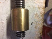
Used ordinary 5/8 11 TPI threaded rod. A brass nut soldered into a post. Works but of course the dial indicator is out to lunch and have to pay close attention that the feed is opposite which is very annoying. At least I could get to use my lathe until parts arrived. Never researched if LH rod was available locally. If this setup was to be used for any length of time it would be worth it.
 

Attachments

  • Temporary cross feed screw mounted IMG_1462.jpg
    Temporary cross feed screw mounted IMG_1462.jpg
    91.8 KB · Views: 76
threaded rod and TA rod pinned together

how the two rods are joined. Short 5/16 pin silver soldered into the acme rod and pinned into the TA rod. Must give credit to my tool and die maker friend who suggested the method. Sadly he passed about two years ago. Sure do miss him. Master machinist and true gentleman from Europe.
 

Attachments

  • Threaded rod & TA rod pinned together IMG_1465.jpg
    Threaded rod & TA rod pinned together IMG_1465.jpg
    86 KB · Views: 100
Just looked up McMaster Carr and they list 3ft length of Acme lead screw rod and brass nuts. A 3 ft piece would make 3 TA rods. 3 brass nuts, (bronze would be better but nearly 4 times more expensive). Price about $66 US. Did not check if in stock. Way back when I purchased two 1 ft lengths of acme rod. They may have cut to lessen shipping costs. Not even certain if parts were purchased from McMaster but as I recall costs were in the ball part.

Its all moot now but if anyone else should run into a similar situation in future maybe this will help.
 
I purchased 15/16 stressproof from Speedymetals. an 8 TPI ACME threading insert from MSCDIRECT as well as thrust bearings.

On Friday I made the 7/16 threaded section at the very end. Then went to turn down the 8 inches of rod that is used to clamp around the T.A. tube. That went OK until I realized that metal to metal spinning at 940RPM generates way to much heat. There are some things that I keep in the house instead of the unheated shop. The grease for dead centers being one of them. Thus I was to lazy to go get it and almost burned things up.

No real issue, just unhappy and ugly.

When I finished turning down that section I went a head and checked for taper. Sure enough 0.007 worth of taper. My tail stock is out of adjustment. It shouldn't have been. But I had a nicely turned rod so it should be easy to correct. Which I did. In the wrong freaking direction.

So things didn't work, so I tried again and ended up with my tail stock way out of position but not so bad that I *knew* it was.

Pulled the work out, took it to the cut off saw, cut it to total length plus 1/4" cause I'm not always good.

Went to face and center drill and broke the center drill. Yeah the tail stock was that far off. Next I tried to cut a center with a boring bar but messed that up. Everything going wrong, time to call it a night. 0047 in the morning.

Saturday I went out, stuck a piece of junk stock in the chuck, faced it down and left a little nub. This gave me enough to be able to get the tail stock almost aligned. Was able to put a center in the rod, put it out to cut the full 11+ inches of the screw part of the lead screw. Turned, measured, adjust the tail stock. Got it close. Still not good, but close enough.

Cut the rod down to 0.625, cut the relief all good. Still a little taper but nothing horrible. Threaded it 8 TPI LH ACME going slow slow slow. 0.005 feed for each pass. Got it close, nut goes on about half way and sticks. Cut deeper. No joy. Finally get peeved and "force" the nut on. Soon as the rod is fully through the nut, it turns smoothly. Since the nut doesn't actually every use that part I figure I can live with it.

Take the old lead screw out of the lathe, put the new one in the mill and realize I'm not sure how I want to hold it. 4.5H in the shop. I call it a day while I noodle work holding.

Today, I went back to the shop, slapped the new screw on top of a parallel, tap it down and put it in the vise. Good enough for light passes, even if I don't have it in a V-block.

0.025 depths of cut with 1/8 HSS end mil. 3.900 inch long key way. Once it was to depth I cut 0.030 more on each side to bring the key way to width. 0.125 total depth required. I went to 0.140.

Take the screw out, test fit, key way is too narrow. Spend 15 minutes getting the screw back in the vice oriented correctly, make the keyway 0.010 wider. Total width 0.125+0.0 or 0.195. Measured at 0.180.

Tried to use the new thrust bearing, of course it doesn't fit through the casting so I used my bronze self made bearing. Put everything together.

Original backlash 0.150 current back lash 0.001. I can't really feel ANY back lash. It is a little tight, but I expect that to work itself out of the next few weeks of use. I also need to get some oil in a few spots which should help as well. (The bronze thrust bearing for sure.)

I got a PM from somebody on the forums that explained why the trust bearings didn't work/fit for me. The original feed screw used a 0.625 section through the TA tube. The TA tube has a bronze bushing at one end and uses bronze thrust washers/bearings at both ends. Because they are just bronze bearings, it is easy enough to just make them to size, which is what S.B. did.

The newer version uses regular thrust bearings. The TA tube is bored to 0.325 (I would have thought they would have just pressed bronze bearings into both ends. The thrust bearings would then have an I.D. of 0.325 which would make the O.D. small enough to fit through the casting.

It was suggested to me that I bore a sleeve to fit in the TA tube. I'm more likely to make a bushing to put into the front side of the tube and make a new feed screw with a 0.325 section through the TA tube.
 
One thing that helps on making a cross feed screw for any lathe is the use of a follower rest. It will allow you to keep the PD of the thread consistent throughout the length of the cut. I've made two cross feed screws for the 13" SBL in my past. The last one I had to recut because I got the thread too thin or way under the PD tolerance for the .625-8 Acme thread. Stressproof is what I used. Another thing I do is rough cut both ends to about .015-.030" oversize. Chucking up on the material and center drill the ends at the chuck, reposition the material to where you are cutting one end at a time. Holding T.I.R. to within .005" end to end is what you are after. That is why to leave it a little oversize, give you a little room to correct any T.I.R. if needed.
BTW- I rough out the feed screws on my 14" lathe and finish turn, using follower rest, on my 9" SBL. Also do the threading on my 9" lathe because it has the lead screw with the most accuracy.. Ken
 
Thanks for the feedback. I don't have a follow rest for lathe. I thought about getting one but haven't yet. Yes, it would help. For the finish passes I just took very light cuts. With 12" or so of stick out with it center drilled and running in a live center, I cut a perfect 0.005 taper. I.e. the center part wasn't thicker than it should have been. All of the error came from my tail stock being out of adjustment.

I did this all in the 3 jaw chuck, because that was what I had mounted. I was originally going to turn between centers but decided it wasn't worth the extra effort.

Chuck up the 15/16 with about 3 inches of stick out. Face and center drill. Advance the center drill and turn section down to 7/16. Thread for 14TPI.

Extend out another 8.5 inches. Take some heavier cuts till down to 0.700 or so (3 passes with 0.050 DOC). Take a series of light cuts till entire section is at 0.625 as nominal size.

Make sure the step from 0.625 to 15/16 is nice and clean.
Turn 0.500 inches down to 0.915 to match original screw.

Take the stock out, cut to length (21 inches or so)

Back in the lathe, face and center drill with 1 inch of stick out.
Extend so that the jaws are gripping on the 0.625 section already turned. If I was worried, I would have used brass shim stock on the jaws to avoid maring.

Take some heavy cuts to get down to 0.700 or so. Make a number of passes to get to final dimensions of 0.625.

Face the collar next to the jaws from unknown to 0.140 thick

Turn 0.500 inches next to the thrust collar down to 0.400.

Set up and cut LH thread at 8 TPI.

I was taking 0.005 cuts with a spring pass every 0.015 inches. So three passes cutting 0.005, then a spring pass or two.

I think I did ok for being self taught.
 
threaded rod and TA rod pinned together

how the two rods are joined. Short 5/16 pin silver soldered into the acme rod and pinned into the TA rod. Must give credit to my tool and die maker friend who suggested the method. Sadly he passed about two years ago. Sure do miss him. Master machinist and true gentleman from Europe.
You could always honor him by naming the repair after him. It will always be something he gave to you.


Back
Top