alienturtle
Aluminum
- Joined
- Sep 7, 2018
I just got done building my 10hp rpc and going through the balance procedure using fitchs document. I basically built this guy to run 2 different pieces of equipment. 1 is a makino rmc55 cnc mill. This mill has all power going through a transformer on the side of the machine and outputting 200v. The 2nd is a 36v forklift battery charger. The nameplate on the forklift charger is 240 at 32 amps
My main question is how do i know if am pulling too many amps through the phase converter since im not really driving motors direct? Do i only care about final amps being pulled through my 3 phase panel or do i need to watch the amps on the 3 wires coming from the pony motor?
Motor is a baldor 10hp. Tag says 240 and 28 amps. Is that 28 amps what i cant go over?
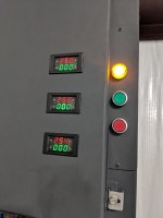
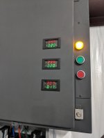
These are numbers idle and with the battery charger running
While the battery charger was running i took amp readings on the 3 wires coming from pony motor
1 was 14
1 was 14.5
1 was 31
I guess im just not sure what i need to watch out for
When i turn the cnc machine on i get almost no amp draw. Im thinking because its going through the transformer?
Thanks in advance. Im just confused.
My main question is how do i know if am pulling too many amps through the phase converter since im not really driving motors direct? Do i only care about final amps being pulled through my 3 phase panel or do i need to watch the amps on the 3 wires coming from the pony motor?
Motor is a baldor 10hp. Tag says 240 and 28 amps. Is that 28 amps what i cant go over?
These are numbers idle and with the battery charger running
While the battery charger was running i took amp readings on the 3 wires coming from pony motor
1 was 14
1 was 14.5
1 was 31
I guess im just not sure what i need to watch out for
When i turn the cnc machine on i get almost no amp draw. Im thinking because its going through the transformer?
Thanks in advance. Im just confused.