Peter.
Titanium
- Joined
- Mar 28, 2007
- Location
- England UK
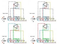
I have bought a machine which has a 3 phase 2 speed motor and I don't have 3 phase power but I also don't want to replace the motor - I want to power it from a VFD which outputs 240v 3 phase. I've got the wiring schematic and figured out that it's a pretty standard 6-wire setup that switches 3 of the wires to be a star point and convert the 4-pole motor to a 2-pole for high speed. Here's the layout:

What I want to do is re-configure the motor to run at the slow speed from a VFD (which is 240v output instead of 415 original supply). Online research suggests that if I run the motor in delta mode same as the slow speed schematic above, but split the two windings and wire them in parallel instead of series, that will be the appropriate configuration.
My plan is to disconnect each pair of windings at the mid-point between phase inputs, one at a time so that I don't make any mistakes, and re-connect them in parallel like this:

If I do one at a time I'm pretty certain that this will keep the winding orientations correct but what I'm clueless about is will it give me the 4-pole 240v motor that I'm expecting or will that not be so? I don't mind giving it the 'suck it and see' approach but I thought I ask right here in case there is something fundamental I am not considering.
BTW I get the machine home next weekend so right now I cannot pull the motor, I'm at planning stage for doing this work right now. I've got the VFD ready to go and the wiring is no problem for me.
What do we think? Is it just as simple as that?
Pete.
What I want to do is re-configure the motor to run at the slow speed from a VFD (which is 240v output instead of 415 original supply). Online research suggests that if I run the motor in delta mode same as the slow speed schematic above, but split the two windings and wire them in parallel instead of series, that will be the appropriate configuration.
My plan is to disconnect each pair of windings at the mid-point between phase inputs, one at a time so that I don't make any mistakes, and re-connect them in parallel like this:
If I do one at a time I'm pretty certain that this will keep the winding orientations correct but what I'm clueless about is will it give me the 4-pole 240v motor that I'm expecting or will that not be so? I don't mind giving it the 'suck it and see' approach but I thought I ask right here in case there is something fundamental I am not considering.
BTW I get the machine home next weekend so right now I cannot pull the motor, I'm at planning stage for doing this work right now. I've got the VFD ready to go and the wiring is no problem for me.
What do we think? Is it just as simple as that?
Pete.