What's new
What's new

220V, 3~, 2-speed motor wiring leads. Correct order?

MyrtleLake

Stainless
Joined
Nov 23, 2008
Location
Chicago, IL
Okay, my de-facto electrician that usually does all my wiring is MIA. I recently had my lathe motor burn itself up. Before disconnecting it, I recorded all the leads from the 2-speed reversing switch to the terminal block on the motor. I then had the motor repaired (full rewind :()

When I received the motor back, the motor shop had removed the terminal block, citing that they often cause problems (no issue with that from me). BUT, they did not record the order of the motor lead connections to the original terminal. I am left with 6 numbered leads that exit the motor.

I tried inquiring with the motor shop, but I didn't understand a word of it. There is a reason I usually leave electrical work to the electricians! :)

Here is what I DO know:
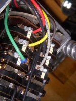
*From the 2-speed reversing switch the red, green, yellow is one speed. The black, black, grey is the second speed. There is also a second green which I know is the ground.
*From the motor, numbers 1,2,3 are speed one. Numbers 4,5,6 are speed two.
*The motor is, specifically: 220V, 60hz, 3~, 900/1800rpm, .5hp/.7hp

Here is what I DON'T know:
*3~ power is run from a RPC. Would you expect the Red and the Grey lines to be the third leg?
*Does it matter what order the three wires from the motor for a given speed and the three wires from the switch are connected? Other than rotational direction?
*A little of a reiteration, but will I damage the motor if the RPC lead is connected to anything other than T3 (speed one) or T6 (speed two)
*I am fairly certain the colored leads from the 2-speed switch are for the slower speed and the Black/grey for faster speed. Still, unsure. But if it was reversed, it would cause no damage, right? To my understanding, it is still the same line current, just activating a separate winding in the motor.

OR
If I get a multimeter, would I be able to answer the questions above with better accuracy? Full disclosure: I have no idea how to use a multimeter.

Help :D
 

Attachments

  • Voegtle_Nameplate.jpg
    Voegtle_Nameplate.jpg
    44.5 KB · Views: 8,251
  • leads1.jpg
    leads1.jpg
    47.2 KB · Views: 34,382
  • leads2.jpg
    leads2.jpg
    60.8 KB · Views: 5,785
  • leads3.jpg
    leads3.jpg
    54.9 KB · Views: 6,224
Last edited:
I am not real familiar with six lead, two speed motors. But I doubt you can damage
the motor by connecting the manufactured leg from the converter, to any particular
lead to the motor.

To start the discussion, can you check continuity between the various wires? This
can be done with what amounts to a battery and a light bulb. I would guess for
starters that any speed "one" wire should be connected to any other speed "one"
wire, so all three are connected to each other, that is.

And that any of the speed "two" wires should ring true to any other speed "two" wire.

The next test would be to see if any of the speed "one" wires, is connected to any
of the speed two wires. My guess would be no.

Can you do those tests? A dry cell and bulb would work, or the 'ohms' setting on
a multimeter would do also. A simple continuity tester from the hardwares store
would have a battery and bulb in it, and would do the job. The kind with a screwdriver
with clear handle, battery and bulb inside, and a wire with an aligator clip on it.

Jim
 
Thanks for the reply, Jim.
I had posted this question on another forum when I didn't receive a response here initially. 220V, 3~, 2-speed motor wiring leads. Order? - The Home Shop Machinist & Machinist's Workshop BBS

I ended up getting a multimeter with phase rotation indicator. I traced the manufactured leg to the RPC to distinguish which lead it was. I made that T3 and T6. Then I tested rotation from the disconnect, after the switch for each speed, and at the motor itself. Then wired all to match.

Works perfect now. I was thrown off at first by a damaged fuse that was intermittently working---and thus messing up rotation, starting, etc.

I also learned this motor is a "Dahlander" wiring. If I understand the wiring diagrams correctly, the switch uses T1, T2, T3 for speed one (T4,T5,T6 are left open). For the higher speed, T4,T5,T6 are used and T1,T2,T3 are all joined together (connected at the switch--not at the motor leads).
 
As shown on the motor's nameplate data, it is a ∆/YY (series ∆, parallel Y) motor, and this configuration is quite common in machine tool motors. This configuration is usually of the constant-torque type.

When operated in parallel Y mode, the motor operates at its higher-rated speed.

When operated in series ∆ mode, the motor operates at one-half the parallel Y speed, and usually with one-half the parallel Y horsepower. The 1:2 speed difference is a consequence of the series ∆ connection having twice the number of apparent poles as the parallel Y connection. It is for this reason that this motor type is appropriately called a "consequent pole" motor.

The High/Off/Low drum switch shown accepts the six leads from the motor and the three leads from the line and effects switching of all the leads to parallel Y, off or series delta modes.

In some machines, there is often another drum switch labeled Forward/Off-Brake/Reverse. This switch simply exchanges two of the lines.

If the motor's leads are not specifically identified as T1, ..., T6, then resistance checks between the leads, measuring T1 to T2, ..., T6; T2 to T3, ..., T6; etcetera; will produce a table of resistance values which will enable T1, ..., T6 to be identified.

On a series ∆/parallel Y motor of this type, there are three exterior leads and three interior leads.

The motor is symmetric about one of the exterior leads, although any other exterior lead will produce the same symmetry.

Once identified, the motor may be connected to the drum switch.

Such a motor is perfectly compatible with an RPC.

Such a motor is also compatible with a VFD, and for such use, the motor is usually permanently connected in high rpm mode, which corresponds to its high horsepower mode.

Four-speed motors of this same type are also known, in which case the leads are identified as T11, ...,T16, T17 and T2, ..., T26, T27, with T16 and T16, and T26 and T27 being provided to open the ∆ on one winding when the other winding is operating.

Three-speed motors usually incorporate a single ∆/YY winding for two of the speeds and a single Y winding for the third speed. In this case, the ∆/YY winding also has T6 and T7 opened, whenever the Y winding is operated.
 
Last edited:
If the motor's leads are not specifically identified as T1, ..., T6, then resistance checks between the leads, measuring T1 to T2, ..., T6; T2 to T3, ..., T6; etcetera; will produce a table of resistance values which will enable T1, ..., T6 to be identified.

As the motor was completely rewound, the leads were nicely identified. If they weren't, however, and I wanted to check resistance as you mention... Would the Ohm values increase sequentially from T1 to T6 or how would you distinguish from the resulting resistance data?

Just curious,
Arthur
 
"Would the Ohm values increase sequentially from T1 to T6 or how would you distinguish from the resulting resistance data?"

The motor is symmetric about the exterior leads, and this axis of symmetry includes an exterior lead and the directly opposite interior lead.

Once you have made a table of resistances, you can immediately see the that the highest resistance is between an exterior lead and the directly opposite interior lead.

Any other resistance measurement will be lower.

For example, should each of the six coils be 1 ohm, there are these possibilities:

1) 3 ohms in parallel with 3 ohms = 1.5 ohms (two occurrences),

2) 4 ohms in parallel with 2 ohms = 1.33 ohms (two occurrences), and

3) 5 ohms in parallel with 1 ohm = 0.83 ohms (two occurrences).

This represents the coil resistance normalized to 1 ohm.

For your own motor, you should see these same ratios, 1.5:1.33:0.83, although the actual resistances would be different.

When you have identified that which you believe is T1 and T5, then check for the next lower resistance, and that will most probably be T1 and T2 or T1 and T3. Next check for the lowest resistance, and that will most probably be T1 and T4 or T1 and T6.

T4, T5 and T6 are connected together and the line is connected to T1, T2 and T3 for YY mode (high speed, high horsepower).

T1, T2 and T3 are unconnected, and the line is connected to T4, T5 and T6 for ∆ mode (low speed, low horsepower).
 
OK, so it was a pole-changing type motor. This is the kind typically found in
the hardinge machines. Those require a pretty special kind of drum switch, that
perform the logic needed to get the two different configurations. Glad it worked out
for you.

Jim
 
When the motor's nameplate states ∆/YY is really means series ∆ and parallel Y. Hence, it also means "consequent pole". This may also be detected by the presence of six wires, and the specification of two speeds, related by 2:1.

The motor is operated in series ∆ for the low speed (also lower HP) and in parallel Y for the high speed (also higher HP).

If permanently connecting the motor in parallel Y, as for a VFD application, T4, T5 and T6 would be strapped across, and the output of the VFD would be connected to T1, T2 and T3.

If permanently connecting the motor for series ∆, T1, T2 and T3 would be unconnected, and the output of the VFD would be connected to T4, T5 and T6.
 
OK, so it was a pole-changing type motor. This is the kind typically found in
the hardinge machines.

Yeah, I have another machine with a 220V,3~, 2-speed motor with two separate speed windings (?). That was the short explanation originally given to me. This one (pole-changing), I would say, is much nicer to operate. It jumps right to speed, even if switching directly to the faster rotation.

I know the other motor with the separate speed windings is correct: It had a full rewind when I first got it. I had the motor shop wire the switch too. In order to get to the faster speed, you must let the first reach full, no load, rotation. Then switch it to speed 2 and wait for full rotation again. The manual even mentions this fact. It seems very lumbering in comparison to the pole-changing type on my lathe.
 
The main reason for employing a "consequent pole" motor is it provides more speeds while using the less "slot space" per speed.

It is also possible to make a two-speed motor while employing two separate Y windings.

However, if using two separate windings, one could also obtain four speeds while using the same "slot space" as two separate Y windings.

The main disadvantage of "consequent pole" motors is these are single-voltage.
 
Peter this board is the only place I've seen the term 'consequent pole' used.
In this case, could 'virtual' be used as a synonym for 'consequent?'

IOW, exactly what does 'consequent' mean in this application?

Thanks - Jim
 
It may also be helpful to the terminology discussion to mention that the original literature for this motor states, "2 Drehzahlen, polumschaltbar, mit Schalter" Literally, in German, "2 speed, pole-changing, with switch."
 
"IOW, exactly what does 'consequent' mean in this application?"

"Consequent pole" is a well-known "word-of-art" in North America.

I do not know the precise origin of the term, but the motor, itself, has n "real poles" and 2n "apparent poles", which are a "consequence" of the motor's internal wiring method.

I believe the word "consequence" was changed, through usage, to "consequent", and applied to the word "poles". Hence, "consequent poles".

There are three extant variations of "consequent pole" motors: constant-torque, which is the usual machinery motor case; constant horsepower; and variable torque.

Each of these has a different internal wiring scheme, but constant-torque is the most common, in my experience.

A search of the "usual suspects" motor controller catalogues would turn up the motor controllers, including overloads, which are appropriate for each such motor.

Oliver, noted as a manufacturer of rather large wood lathes, which are actually pattern-maker's lathes, has a patented motor controller which supports four speeds with a direct-drive headstock.

An interesting characteristic of this motor controller is the line connection is automatically broken before the load connection (and, I should add, that there is overload protection appropriate for each of the four speeds), and this characteristic lends itself to using a VFD as a phase converter as well as a variable speed drive system.

I have published a simple modification to an Oliver pattern-maker's lathe which takes advantage of this characteristic.

See this ...

http://www.practicalmachinist.com/vb/875157-post13.html

... post, for the details.


Back
Top