What's new
What's new

240-460 transformer wiring

waynes

Cast Iron
Joined
Mar 5, 2011
Location
Trenton, On
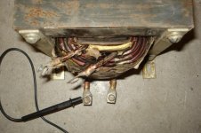
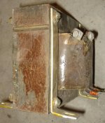
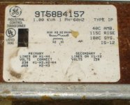
Since I now have two working 460V VFDs and only one transformer to feed them, I went back to the scrap yard today. Found two transformers that I think might work to feed the VFD. Heres a pic of ones wiring diagram and a pic of the other (no wiring info at all).
012.jpg007 (2).jpg

After some reading on this site about similar attempts, seems the transformer with the wiring diagram can't be fed 240V to the 120V windings as it would go into saturation.

The other is apparently 1 to 1, just over 6 inches square, and is wound with .150" square copper for both windings. It was with some Gettys N350 servo drives - but I don't know what specifically it was used for (I did bring home the 3 complete drives). The 1:1 was found by feeding 125V into one winding and measuring 125 at the other winding.

I'm thinking this could be wired as an autotransformer to make it a 1:2 transformer. The terminals are just labeled 1,2,3 & 4. So I'm thinking line goes to 1, other line goes to 2 and 3, and the output is from 1 and 4. Is this correct or did I fail with my reading comprehension?

Actually I don't know if the junction between the coils should be 2/3 or 2/4. What happens if it's wrong? I'm thinking the output would then be near Zero between 1 and 4???

Wayne
 
The first one could be used as an autoformer, since it is 230/460. Wire it 460, and feed one side of that the 230V. Ignore the 120V output.

The other one is unknown as to voltage, current, or anything. That general size is usually between 500VA and 1 kVA. It most likely is for lower voltages, with that size wire. A view of the end of the laminations, the side as it faces in the pic, would reveal if there is any sort of gap put in the core. It doesn't appear so, but this is as well to check in a case where the wire size seems out of proportion, it might be an inductor (it could be one and still have worked as a transformer for a short time).
 
JST, OK - I was wondering if the two coils of the transformer with the wiring diagram could be used that way. I'll give it a try.

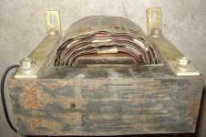
The one with no info has 4 layers of windings - here's a couple top view photos of the windings:

001.jpg002.jpg

Not sure what you mean by gap - between the winding layers - in the core?

Wayne
 
N350 was scr servo drive for dc motor..typically like 160vdc output..... iircn it used bifilar wound abt 3mh dual choke on output - the unit u have.... I could pull n350 wiring dia and send to u if u email me and want it.

Would love to have the wiring diagram! I just got them today, but my initial searches have pulled very little info on the drives. I think you're right about the transformer looking thing being the choke for the drive. I'm guessing there's not enough windings to use it as a transformer? Too much like a short circuit?
 
If you look at the sides, the view not in any of the pics, you may see that there is something other than iron in the gap between sets of laminations. That would mean Mike K is correct and it is an inductor, as I suggested it might be.

More likely with the top view NOT showing any interleaving of E and I laminations, It looks like all "E" type are together and thus all "I" type on the opposite side. There will be some material spacing the I away from the E lams, to adjust the inductance and prevent saturation of the iron, by putting an air gap in the magnetic path..

Right you are JST! I didn't notice the gap in the laminations and misread your first post thinking the gap was between windings. Here's the photo from the side showing the laminations and gap.

Inductor side.jpg

I screwed up yesterday when I thought it was working as a 1:1 transformer. I was actually just reading line voltage through the inductor coils. I did try wiring it as an auto transformer with a light bulb to restrict current between the two coils to see what it would do. With 125 volts on terminals 1 and 4, light bulb wired between 2 and 3, it showed 1.4 volts between line 1 and 2 (step down autotransformer configuration if I have it right). So very little transformer action going on. I have no idea why.

I wired up the 1 KVA with the wiring diagram as you suggested and it runs the VFD just fine. Of course it won't give full power, but I don't need that with this one - it will be running a 1/2 hp Clarkson grinder motor. Ran the motor for about an hour today with nothing showing more than about 15 deg C temp rise. Thanks very much for all your inputs!

Wayne
 
Would love to have the wiring diagram! I just got them today, but my initial searches have pulled very little info on the drives. I think you're right about the transformer looking thing being the choke for the drive. I'm guessing there's not enough windings to use it as a transformer? Too much like a short circuit?

Just scanned in & emailed complete manual to you; it has complete wiring diagrams, and shows this dual inductor.

Hope your hotmail account can accept the 700kb attachments.
 
Just scanned in & emailed complete manual to you; it has complete wiring diagrams, and shows this dual inductor.

Hope your hotmail account can accept the 700kb attachments.

Got the scans. Thanks Mike, that's terrific! Very much appreciate you going to the effort of scanning it for me. It's guys like you putting in the effort in answering questions and providing your hard earned knowledge that really make these sites great.

Wayne


Back
Top