What's new
What's new

2HP repulsion start induction motor using increased current, trips motor linestarter

bkc

Plastic
Joined
Sep 8, 2021
Hi,

I'm a trustee for a small church with an early 1900's 2HP Century Repulsion start induction single phase motor driving a blower for our organ.

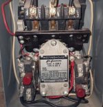
It's controlled by circa 1956 Westinghouse life-linestarter class 11-200 3 phase Type N (wired as 2-phase 3-wire circuit)

The linestarter is fed through a double-pole fusebox with (2) Type T 15 amp slow-blow fuses


In the past two weeks we've encountered a problem with the motor. After about an hour of operation, the linestarter trips.

We sent the motor to a local motor/pump repair company

They:

  • cleaned armature & grooves where brushes run
  • adjusted brushes
  • tested all coils for opens/shorts to ground, shorts to other coils
  • checked bearings
  • replaced oil in bearings

Despite this, the motor controller still trips.

I've found a note on the controller that claims in 2012, startup current was about 45 amps and run current was 10.0 amps and 10.5 amps (L1 & L2)

This week (after repair) I measured the current using two different meters and found startup current to be 45/43 amps (L1 vs L2) and run current is 14.7 and 14.2 amps. (there is a 600 watt DC transformer on L1, accounting for the addl 0.5 amps)

The clamp meter I used claims an accuracy of 2% + 6D (I'm not sure what 6D means)

I have no idea how accurate the the notes from 2012 are.

Between L1 and L2 its 241 volts (motor not running)

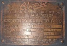
The motor nameplate indicates it will use 12.5 amps at 220 volts


I ran the motor for 1.5 hours w/o tripping by leaving the cover off the linestarter box.

I used an IR camera to measure the temperature change of various parts of the motor.

The top of the motor housing increased from 70F to 120F (a 27C change)

The stator increased from 70F to 150F (a 44C change)

The motor nameplate says a 40C rise is allowed. Would this be the temperature change of the frame, or of the stator?

I spoke with the organ repair company and they explained how the blower and airbox work. Essentially the blower is always pushing against the spring pressure of the air chest. The only way to increase the load on the motor would be to restrict the air intake. However the air intake is not restricted.

The linestarter is currently using size BE14 heaters, theoretically a 125% overload protection range of 11.9 to 12.8 amps

Can anyone answer these questions?

1. What else should we check to track down why the current load has increased in the past 9 years?

2. Since the protection range of the heaters is 11.9 to 12.8, does this mean they are slightly adjustable? If yes, how would I adjust them?

3. Would it be acceptable to go to the next larger heater, BF16 12.9 to 13.8 amps?

Thanks for any suggestions you may have.

Here's a video of startup and shutdown https://youtu.be/HBPSiir-a-8

motor-nameplate.jpg

linestarter1.jpg

linestarter2.jpg

linestarter3.jpg
 
An initial thought here is that "load" on a typical "blower" is actually LEAST when it is not moving air. Typically it is loaded the most when the airflow is completely open. When the blower is not moving air, it can run free just "whirling" air, at it's normal rpm. When it is totally open, with no restriction, it must move a lot of air while maintaining rpm.

That depends on the type of "blower" it is, most common types known as "blowers" will follow this. The problem is that an organ may call anything that provides air a "blower", even what most would call a "pump".

A "pump", like a piston type air compressor, is the opposite of a typical "blower", it draws more power trying to force air into a tank that is already at a high pressure, than it does just moving air at low pressure.

An organ may use either type. What type of "blower" does this organ actually use?
 
From the video, it definitely looks like a centifugal blower of some sort. I am not sure whether forward- or backward-curved blades makes a difference for this.

It appears that this is direct-drive, so presumably there is no chance for a belt ratio to have been adjusted.

Is the supply voltage about right? Transformer tap changes or loose connections could have changed the supply voltage.
 
Yeah, there seems to be a pipe leading up, and a round housing. The pulley in front looked as if there was a drive to some mechanism, and I did not look closely.

It appears to be not a squirrel cage, but likely a centrifugal blower more like a dust extractor or large vacuum cleaner. That will act like any other centrifugal blower and have the heaviest load at the highest volume flow, with very low load if flow is blocked.

In that case, there could be extra load if there are leaks in the air system. That would increase flow, but the pressure might not drop much. With more flow against pressure, more power would be needed.

I'd expect power draw to be the least with nobody playing the organ, and therefore less air flow. So leaks, or some fault in whatever system maintains the air box pressure could account for extra power.

The motor is repulsion start, but is an ordinary induction motor once started. It shows an FLA of 12.5 A, but is drawing about 14% more. There may be some extra load. Judging from the coast-down, the motor and bearings etc are fine.

It is a 110/220 motor, and input is stated as 240V. That might add some current draw by itself.

But the motor temp is stated as 120F (50C). Even giving it another 20C for hot spot temperature, that does not seem to be excessive for the likely insulation type.

Could be leaks giving extra load. Could be the heaters in the protector have corrosion under the screws and are heating more. The starter looks clean, though.
 
The motor is repulsion start, but is an ordinary induction motor once started. It shows an FLA of 12.5 A, but is drawing about 14% more. There may be some extra load. Judging from the coast-down, the motor and bearings etc are fine.

It is a 110/220 motor, and input is stated as 240V. That might add some current draw by itself.

Hi,

Thank you all for the great comments so far.

Given my basic knowledge of DC circuits, I would think the current draw would go down when the voltage increases, assuming the same total power is being consumed. That is, I would assume a 9% increase in voltage would result in a 9% decrease in current. So instead of 12.5 A it would be about 11.4 A

Do AC motors not work that way?


Could be leaks giving extra load. Could be the heaters in the protector have corrosion under the screws and are heating more. The starter looks clean, though.

Here's a closer view of one of the heaters. I had removed a screw so that I could read the code. The screw side of the heater was clean. I can remove them completely to check them. There does appear to be a color difference nearer the screws.

Do heaters wear out over time? I haven't been able to find a description of their failure modes.

Would it be useful to get a tachometer and measure the actual RPMs?

I will scout around to see if there are air leaks in the organ room.


linestarter4.jpg
 
Higher voltage is less current for same power, simple ohms law math...but the motor resistance is same with increased voltage so we assume higher voltage would mean higher current with same load.

We are not a motor expert so we may be wrong here, others may be better at it.

Voltage is 10 percent higher as is current so maybe okay.

Your measurements indicate the current is greater than the heater so they are working as designed.

I would consult the company that worked on the motor as they should have tested it as part of their service.

They should be able to confirm how your measurements compare to expected performance.

It very well could be that years ago line voltage was lower as it generally was and maybe recently raised a bit due to other construction in your general area.

Your motor if running at full load seems to indicate other problems as one would assume the manufacturer would have had some headroom in the build but motors were expensive in the day so maybe not, more homework for you.

Sent from my SM-G781V using Tapatalk
 
Typically, the current at no load would be expected to go up somewhat with voltage. More, if there is any magnetic saturation, which is possible, but that is usually not excessive at only 10% over nominal voltage.

Yes, constant power could actually draw less added current due to the load. That would offset to some degree any added current due to magnetic effects.

It is entirely possible that there is more than one effect operating here.

I'm not as concerned about it as I might be, since it seems relatively low excess current, assuming the meter is accurately showing the current. I don't know if the meter is true RMS or averaging.

But, since this is current when the organ itself has no airflow (correct?), I'd expect the motor not to draw FLA.

Not knowing how the constant pressure is maintained, I assume there is some sort of release valve. That would have the same effect as leaks, or normal airflow when playing the instrument. Air pressure can affect the way the organ responds and sounds, so a constant pressure may be desired.

It is, however possible that there is some type of air chest that simply holds air at whatever pressure the blower can maintain. In that case, the needed power would presumably drop somewhat if the blower is on with no pipes in use.

If the question is why the motor seems to be drawing excess power/current, it seems as if we need to know the way the load works. The difference between having a pressure valve, or just having blocked airflow, could be important.

By the look of the video, there is no mechanical problem with the motor or impeller etc that would be causing friction. It took quite a while to spin down.
 
A 600 watt transformer running on 240 volts draws 2.5 amps, not 1/2 amp.

Remove the transformer from the circuit and see what the current is then.
 
Overcurrent protective devices always trip for a reason. If the motor has run fine for the last 100 years but only recently began to trip on overload, chances are something has changed and it *is* now in fact overloaded.

Have you tried decoupling the motor and running it without load? I'd be willing to bet it will run well within it's nameplate current in that state. 99% of the time overload conditions are a result of an issue with the load rather than the motor.

Check all bearings for wear, drag and alignment. Inspect the blower for correct operation. If it is not throttled and is being allowed to run 'wide open' then that's probably the issue. Centrifugal blowers consume more power with increased throughput. They consume minimum power with their intakes baffled shut and/or back pressure on their discharge ports. Note that not all blowers can handle the vacuum pressure created by intake throttling - some are intended for discharge throttling only.

Are there any new air leaks that might have developed in the discharge piping for this blower?


Also for the sake of preserving an antique, please realize that your motor could use some commutator service. The sparking during startup borders on excessive and may damage the commutator over the long term if it worsens. A competent motor shop would have recognized this and corrected the issue before sending it back to you.

Here is an example of a Century whose commutator and brushes are in proper trim:

Dropbox

Can you see and hear the difference? No hot pops or sparks except during transition. My guess is your motor shop either cleaned a damaged commutator without skimming it, or did skim it but left ragged edges on the commutator segments, e.g. by neglecting to undercut and deburr them. If the latter case, it may 'wear in' and go away on it's own. If the former case, it will only worsen.

I would inquire to the shop to see which case you're dealing with. In the latter case it might be possible to alleviate the issue by stoning the commutator with a special dressing compound made for this purpose. The name of it escapes me for the moment.


EDIT:

Also, check line voltage. Possible the utility made changes in the area and your line voltage is now high.
 
Hi,

Thank you all for the great comments so far.

Given my basic knowledge of DC circuits, I would think the current draw would go down when the voltage increases, assuming the same total power is being consumed. That is, I would assume a 9% increase in voltage would result in a 9% decrease in current. So instead of 12.5 A it would be about 11.4 A

Do AC motors not work that way?


Here's a closer view of one of the heaters. I had removed a screw so that I could read the code. The screw side of the heater was clean. I can remove them completely to check them. There does appear to be a color difference nearer the screws.

Do heaters wear out over time? I haven't been able to find a description of their failure modes.

Would it be useful to get a tachometer and measure the actual RPMs?

I will scout around to see if there are air leaks in the organ room.


View attachment 328729

Check all the connections in the starter. It wouldn't hurt to take the heaters off and clean the connections. It is possible that they could just need replacement. Not sure if you can find them for a starter that old. You might try Ebay. My .02.
 
Guys. 600 watts is almost a horsepower. If the power suppy mentioned is tagged on the motor, that's why the OL is tripping out.

The linestarter has 3 legs, L1, L2 (common) and L3

L1 and L3 feed the motor at 241 Volts

L1 also feeds the transformer at 120 Volts

transformer.jpg


I measured the motor current twice.

First I measured it directly at the motor, downstream of the linestarter, using a 'cheap' analog clamp meter. This does NOT include the transformer.


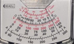
here is one leg, after running for for 1.5 hours, using the 15 amp scale. This looks like 14.0 amps (+/- I don't how much.. 5%?)

motor-amps1.jpg

Here is the other leg, about 13.5 to 14.0 amps

motor-amps2.jpg


The 2nd measurements came from a better (still kind of cheap) digital clamp meter, measuring the inputs to the linestarter. Those measurements include the transformer.


I reported the 2nd measurements in my initial post, 14.7 and 14.2 amps

I used a harbor freight Ames 1000A AC/DC TRMS ('True RMS') meter. The manual claims AC current accuracy +- 2.0% of rdg +8D (what's 8D?)

I can't afford a fluke meter..


The '2012' readings of 10 and 10.5 amps come from this note written on the linestarter cover

linestarter5.jpg

I will check the organ room for leaks.

I will also take a look this weekend to see how difficult it would be to temporarily remove the blower from the motor to check the no-load current.

Also for the sake of preserving an antique, please realize that your motor could use some commutator service. The sparking during startup borders on excessive and may damage the commutator over the long term if it worsens. A competent motor shop would have recognized this and corrected the issue before sending it back to you.


Thanks for the video, I can see there is a big difference in the operation of your motor vs our motor.

We are in a rural area with not many choices for electric motor service. I will think about how to bring up this subject with the repair company in a 'nice way'.

I think I'll start by asking them what current they read when they ran the motor in their shop. Hopefully they still have it written down somewhere.


--

For those curious how the air is regulated, when I spoke to the organ repair company, they described the air reservoir as spring based bellows with an input choke. As the bellows expand to maximum capacity a valve closes to inhibit air entering the reservoir.
 
Check all the connections in the starter. It wouldn't hurt to take the heaters off and clean the connections. It is possible that they could just need replacement. Not sure if you can find them for a starter that old. You might try Ebay. My .02.

Hi,

I actually found the next larger size heater, BF16, on ebay and ordered 2 of them "just in case".

I will take the BE14 heaters this weekend and maybe apply 400 grit on the contact surfaces
 
If there are leaks, then odds are the valve to prevent air from coming in won't close.

If it DOES close, the motor current ought to drop when blower output is blocked (assuming it is not sent to a "waste gate", but really is blocked).

Guys. 600 watts is almost a horsepower. If the power suppy mentioned is tagged on the motor, that's why the OL is tripping out.

The question is really what the LOAD on the transformer is. It will only draw what it has to. Easily solved by measuring the transformer current.
 
The question is really what the LOAD on the transformer is. It will only draw what it has to. Easily solved by measuring the transformer current.

I did measure the current feeding the outlet that the transformer is connected to, by tapping the corresponding line on the L1 output terminal

in rush 11 amps, running 0.39 amps

Also, earlier tonight I posted a reply that includes current measurements directly at the motor, but I think that post is waiting for moderator approval since it includes pictures.
 
No, you are not on moderated status. It's "up".

Strange, when I posted a response with direct motor current readings, photos of an analog clamp meter, the website said my post had to be reviewed by a moderator. That post still hasn't appeared..
 
It was useful to learn that increased airflow results in increased load for the type of blower we have. The suggestion to look for leaks was a good one.

I found a sizable leak as shown in this video.

Shared album - brad clements - Google Photos


The 'air chest' is in fact a room about 9x6x8'. The entire back wall forms a bellows. The wall is spring loaded. This video shows one corner of the bellows has been torn open, the black metal bar is one of the springs.

If there wasn't a hole here, the wall would move outward about 8" to compress the springs. That movement would pull a bar inside the air chest that would then close the intake valve from the blower.


When we get this repaired I will follow up in this thread with new current readings.


Thank you to everyone who commented on this thread!


Back
Top