What's new
What's new

3 phase, multiple speeds, barrel/drum switch

Shawn_Laughlin

Aluminum
Joined
Mar 28, 2019
We have been putting bandaids on this abused,ragged out set of Bertsch & Co. supposedly 5/8 x 12’ plates rolls since I can remember. It’s old American iron that Had seen much better days. The gear journals that are bent and the gears wobble all over the place when rotating,it’s quite a show.The bushing are so worn out it’s absolutely ridiculous to think this thing can produce a round shell but, I do so until something catastrophic happens it won’t be replaced. So another bandage it is and there is no better place to learn than this website an it’s genius members. Yes I’m kissing ass to get help but it’s not a lie.

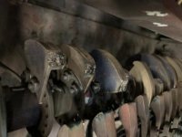
I know a little about how 3 phase speed is driving digitally but not so much about the correct series of mechanical links of contact timing in order to not have arc blow and quickly eating away the fingers and rotary contacts when contact is made. Basically if you have three wires ,your 3 phases should they all make contact at one time like a beaker switch or should it be one makes contact and while still in contact the second phase contacts and then while those two are still in contact the 3rd phase can roll around and make its contact without causes arc flashes which are destroying the fingers and rotaries. Pictures below you will see some have no signs of arcing so it would seem the the rotaries are not set up correctly?

DD947387-D7C3-43B7-A7FC-FC3F921EF4EF.jpgimage.jpg8F27172D-9A65-4144-8796-63C4247C496B.jpgC3B6C010-4124-484B-B9F9-560DE8EBE724.jpg03966E94-F129-46D6-B747-BDE0BCE71119.jpg

I would also really appreciate someone explaining to me how these multiple speed 3 phase reversing barrel switched work?
 
So, your photos are showing the switch? I count 15 contacts. With three phase, that perhaps is 5 sets of three. And it controls both direction and multiple speeds? It is most likely a custom design for that machine or perhaps for a line of machines made by the same company. And I bet the guy who designed it was proud.

I don't know exactly what you want to do with it. If I were confronted with "repairing" it I would look into replacing it with a handful of contactors and either dedicated logic circuits or a microprocessor to control them. Some push buttons to control it: forward, reverse, speed 1, speed 2, ... and Off. Or something like that. I guess it could be controlled by a rotary switch also.

As for how, I would want to look at a schematic diagram of the circuit. That schematic probably needs to be created as you would be lucky to have even a wiring diagram (which I consider very confusing). I would probably have to trace the wiring and make that schematic drawing.

If you want to repair that OEM switch, you will need OEM parts (if they are still in business and have stock) or make the needed parts.

As for your question about the three phases being sequenced or making contact all at once, normally there is no reason or need for sequencing them and doing so would energize one or two windings, creating heat until the final windings are energized. Normally all three phases are connected at once: no sequencing. I have never seen any exceptions to this, but I haven't seen everything. Only way to get a really definitive answer to this question is to ask the OEM.

Good luck.
 
Maybe...just maybe you could buy a case of solid state relays, and put microswitches on the cams.

Thereby keeping the cams for the logic, and the microswitches xfer that logic
to the solid state relays, no more sparking.

But I'll defer to "them that's doing".
 
I use to rebuild the contacts with silver dimes and silver solider, and then machine back to size, this requires the complete tear down of the drum switch. You might get lucky and find parts on ebay, looks like a old GE. The motor has different winding's with lots of leads and the hook up will let the motor work as a 4, 6, 8. 12 pole motor IE multi speed. You will need a wiring print to hook it up, 20 or more leads if you want a job from hell just mix up the wires.....Phil
 
Yes, Phil brings up a great point. DO NOT disconnect any wires without putting a label on them FIRST and recording exactly where they were connected.

All too many times I have seen things disconnected with the assumption that "any tech" should just know how it goes back. I have worked on an awful lot of equipment, electric and electronic, and can tell you that is just not true.
 
Ya there nothing like trying to wire up a 4speed motor when all the wires are not marked, you have to pull the end bells and rotor out and ring it with a compass....Phil
 
I worked for GE General Purpose Control. That switch was not made there. It may have come out of the Industrial Control unit. The catalog number would start with IC. That doesn't help though.

I am surprised there are no arc chutes. What is the operating current and voltage on these switches? The erosion on the leading edge of the three or so moving contacts is do to arc erosion as the contacts slide together. If you want to continue to use the switch, those can be either repaired or replaced by having new ones made. I doubt there are replacement parts available but I have been wrong. In order to repair or replace them the switch would have be taken out of service for a period of weeks.

If you want to replace the switch with more modern control, it could be done. We would need to know the logic to design a circuit.

Tom
 
If it were mine I would be installing a VFD drive and the appropriate controls. Likely the conversion to contactors or the rebuilding of the rotary switch will be in the same ballpark price as the VFD.
Actually after looking at fleabay for 20hp drives that is the only way I would go... plenty of new ones for 1K or less. Many have multiple speed presets all you would need is a rotary selector, an on and off button and some Estop switches. Or better yet a hand held pendant with a speed pot (speed control from 0 to 100%) and a momentary enable buttons (forward/reverse) and estop. 1500 bucks in parts give or take a few and "bobs your uncle". You will have 2x or 3x that in contactors and relays and figuring out all the circuitry. I would not mess with rebuilding the old selector rotary switch on that machine.
 
I wonder about that motor.

Does it have a set of brushes and slip rings at one end? An old-time way of changing speeds had a wound-rotor motor, and different resistors connected to the brushes that were cut-in, or shorted depending on the speed wanted. It essentially varied the slip and so the speed at a given load..
 
If it were mine I would be installing a VFD drive and the appropriate controls. Likely the conversion to contactors or the rebuilding of the rotary switch will be in the same ballpark price as the VFD.
Actually after looking at fleabay for 20hp drives that is the only way I would go... plenty of new ones for 1K or less. Many have multiple speed presets all you would need is a rotary selector, an on and off button and some Estop switches. Or better yet a hand held pendant with a speed pot (speed control from 0 to 100%) and a momentary enable buttons (forward/reverse) and estop. 1500 bucks in parts give or take a few and "bobs your uncle". You will have 2x or 3x that in contactors and relays and figuring out all the circuitry. I would not mess with rebuilding the old selector rotary switch on that machine.

Yah. Two ways, modern tech:

- Stout VFD, NEW motor that had but ONE set of windings.

ELSE:

- DC motor, 4Q DC Drive.

Either one can be stepless variable. Either one can use presets. Either one can be pendent or even wireless remote controlled.

4Q DC can generally reverse faster as it uses the grid rather than braking resistors.

Downside? DC motor prices, 5 HP and above, are generally beyond reach of ordinary mortals unless..

.. found used-but-good, used-rebuilt, not put back into service, but held as spares, or - rare, but I have bought several - New, old stock. Not dealer stock. They didn't.

Some long-gone enterprise with the critical need to stock shelf-spares that never got used.

Bottom line: AC + VFD is more economic.

CAVEAT: It will "probably" be necessary to upsize the motor and VFD.

The existing rig might be tired and ugly, but it was probably rather good at what it did.
 
It may be possible to use a VFD with the existing motor. You'd need to find out what the torque, speed, and duty requirements were for each option. That would probably be necessary for replacing with any new motor too.

An alternative to reconditioning the switch is to simply use enough contactors to emulate it, with either relay logic or a PLC doing the switching. Possibly the cheapest parts option here, but could take some design work.
 
I didn’t realize so many people had posted so many actual helpful responses. Thanks guys. Ima try to answer everyone.
 
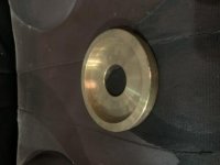
EPAIII,yes it controls forward,reverse and honestly don’t know how many speeds as is it’s never really had any kind of sped control except fast and throw in reverse stop. I’ve completely dissembled this thing before and absolutely had to label every wire. We had a bunch of the fingers made and had a guy take the rotaries and built them back up and machined to shape. The second time which was not a year ago and the machined just bought some extra extra heavy wall brass tubing,I think “which I thought was a poor choice of material” and turned them gown to the right diameter and bore, cut to thickness and then turned the recess and lastly cut in pies of correct size.

Something was just never right. At first it was fine but it was only two speeds,medium fast and fast,there but never a low speed.
And I could be wrong about this but I don’t think the rotaries make contact with the fingers at the correct time bc of how bad they have eroded from the arc in a pretty sure time? What’s got me thinking that they aren’t timed correctly is most have very minimal to no arc damage but, others are damaged beyond use?

But to answer about what im wanting to do or know is, I really would like to know why some contacts are chewed up but some show no signs of usage?

I would imagine there is a certain sequence these are suppose to make contact with the fingers so you don’t have arcing but arcing would be inevitable once enough material was removed from the leading edges of the contacts points from sliding friction to alter that contact sequence or timing? Is that a correct assumption?

Here a picture of the uncut rotary contacts

EE6F7146-ACC2-494E-9ACF-9EF37FB2092C.jpg
 
Digger Doug, to the non electrician that Would be a valid suggestion and I am one of those. I could see some roller micro micros with being used on in place of the fingers and have the original rotaries still being used. But I’m no electrician.
 
Phill, thanks for the reply. I’m not Einstein “even though I mistakenly thing I am sometimes” but my daddy did teach it’s better to be safe than completely F-ed, hahaha,so yes, if/when I take this thing apart I will most definitely label every wire and mark the holes for the rotaries and take a million pictures. That’s how I built and installed my f150’ 5.4 3v 5 years ago and hasn’t really ran right since,even with the whipple supercharger but,hey the transmission I rebuilt is good.lol.

Anyways back to seriousness,there are no labels or maker marks remaining anywhere on this thing. I only know it’s a Bertsch and Company 5/8” x 12’rolls.
 
TDegenhart, first off thanks for the reply.i have no idea what the controls are suppose to operate with but do know I trip an 80 amp breaker and almost spit the plate out of the rolls when I do an emergency throw in reverse to stop. The motor has been replaced probably 3 times and it seems like each time they go with a smaller motor. I was here for one of this replacements about 17 years ago. I think originally it was a 30hp or maybe bigger,then a 25 and it migrated to a 20hp.

As for a volts, it runs on 240 but I beleive under the cover of the piece pictured below is a 240 to 460 transformer and the motor wired 460.
This place isn’t shutting the shop down unless it’s got 3 broke legs and arms and hasn’t been breathing for two days and even then they will be thinking about it.
.
 
If the motor has been replaced, it is unlikely to be what I suspected, as wound rotor motors have not been in general use for many years.

Two speed motors would be fairly easy, as a Dahlander winding would give a half speed and full speed, and uses fairly simple connections. If the machine has had just two speeds for years, it may have had a two speed motor installed years ago, and the wiring may have been changed to operate that. If it had originally had a three speed motor, there may now be unused contacts that might possibly be used to swap with worn contacts.

The timing COULD be an issue, for a couple of reasons. The non-burnt contacts might be ones that are not used with the motors now in use, or three of them might be ones that make the "wye" connection for the Dahlander motor, and may be connected first before power is connected. They would, in any case, carry lower current than the main power connections

As for the timing, once a contact is burnt, and connects late, the other two will make a connection that "single phases" the 3 phase motor. The motor will not turn in that condition, and will draw a high current. The motor will not run until the third contact closes.

That does happen even in the normal condition with good contacts, but not for very long, it is just the impossibility of making the contacts all close at exactly the same time. So contacts of any material will eventually need to be replaced. That will be sooner as the contacts start to wear and close late.

Brass does melt at a significantly lower temperature than copper, and does not carry away heat as fast. It looks as if the original contacts are copper. Using brass would very likely increase the rate at which the contacts wear away and fail. Once one starts to wear away, then there may be more stress on the others.

It would be best to replace the contacts with the same material (copper, it looks like) that was used to begin with. Unless of course, the management would go for an actual overhaul and change to a more modern system, which sounds unlikely.
 
TDegenhart, first off thanks for the reply.i have no idea what the controls are suppose to operate with but do know I trip an 80 amp breaker and almost spit the plate out of the rolls when I do an emergency throw in reverse to stop. The motor has been replaced probably 3 times and it seems like each time they go with a smaller motor. I was here for one of this replacements about 17 years ago. I think originally it was a 30hp or maybe bigger,then a 25 and it migrated to a 20hp.

As for a volts, it runs on 240 but I beleive under the cover of the piece pictured below is a 240 to 460 transformer and the motor wired 460.
This place isn’t shutting the shop down unless it’s got 3 broke legs and arms and hasn’t been breathing for two days and even then they will be thinking about it.
.

Well.. it was probably a rather elegant rig.

When NEW.

Complex mechanical switching used to be more common "back in the day" before not only Solid State, but even prior to decently implemented "relay logic" doing the heavy thinking for ignorant, but tough "commodity" - hence easily renewed or replaced - contactors.

The "complexity" stayed with the longer-lived microwitches and relays. Those, too, were "commodity" items, individually, and widely stocked. The "decision maker" a mechanical plate-cam - multiple sections built-up as needs required. No electricity reached its cams at all.

Some of the old rigs were called "music box" switches, they had so many complex "modes". Timing them was a mechanical skillset - even akin to composing music - more than electrical.

The problem you have NOW is that it has been cobbled one or more times "too many".

Fair chance the present motor doesn't even OWN the full complement of complex windings that switch was matched with, originally. Two-speed, ONLY, sounds like what it has been replaced with?

I'd put this one in its current state of successive degradation into the classical "Gordian knot" category.

Rather than spend the seriously non-trivial time to "unravel" its mystery, only to confirm you need a special motor no longer to be had? I'd cut it. Out. Altogether.

Your OPERATIONAL USE needs plenty of torque, all speeds, coming off the mark especially - variable speed, fast if not "instant" - or near-as- dammit - stopping and reversing?

All with a touch of smooth FINESSE, not herky-jerky rude surprises?

That's all Dinosaur Current's game.

VFD + 3-Phase with one-speed motor needs typically DOUBLE the motor nameplate and an Industrial-grade VFD to match to deliver-up the starting and low-speed torque inherent in a DC rig.

In the very DNA of a tough shunt-wound DC motor and suitable controller that be.

Think hoists. Elevators. Machine-tools with "that certain sort" of demand.

One motor. Reduction ratios as-had to suit the rolls. Reliance RPM III my bias. Second-choice GE Kinematic. Used can work.

One off the shelf 3-Phase-only DC drive. Current production goods, even if bought used-but-good. Major maker in any case, not another "orphan" nor "boutique" maker.

Single knob or pendant control for direction, speed, and stop.

It's a "niche application", surely. But the very niche Dee Cee are REALLY GOOD AT, even if AC+ VFD have eaten most everything else that "servos" have not.
 
Without comment on future plans, brass is a terrible material for a contact. High resistivity, easily welded among others. Pure copper or alloys like cad-copper or chrome copper were standard contact materials until silver came along. The contacts with high erosion are probably the reversing contacts.

As Thermite has said, the best application is DC. That is how all the mills of yesteryear were built.

Some of contacts on the drum are probably control meaning low current. I would think that the panel could be rewired to use these contacts to drive solid state contactors. Another option is to use mechanical contactors. If you go this route, do not use IEC contactors unless you carefully derate them. They aren't designed for this type of duty without deratings. The old NEMA contactors will work, but not necessarily the new ones as the new ones are mostly rebadged IEC or redesigned to the IEC concept.
Tom


Back
Top