What's new
What's new

3 Wire Single Phase Motor Connection/wiring?

Machinery_E

Titanium
Joined
Aug 19, 2004
Location
Ohio, USA
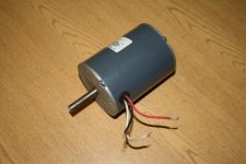
I have this motor that would be perfect for a project I'm working on, the problem is I can't figure out how to wire it, with what I am assuming needs to be a capacitor? Got it like its shown so I'm not sure how it would be connected? Any ideas? Thanks so much for any help!
 

Attachments

  • IMG_4786.jpg
    IMG_4786.jpg
    38.1 KB · Views: 2,475
  • IMG_4787.jpg
    IMG_4787.jpg
    45 KB · Views: 10,430
I've seen 3 wire single phase motors on tool changers. Usually the 3 leads means they are reversible. One wire is a common. You apply power to one of the other wires depending on which direction you want it to go. Some can also do braking by using both windings at the same time.
 
I've seen 3 wire single phase motors on tool changers. Usually the 3 leads means they are reversible. One wire is a common. You apply power to one of the other wires depending on which direction you want it to go. Some can also do braking by using both windings at the same time.

this is definitely a capacitor start motor, with "4MFD/370VAC" being the specs on the cap. that being the case, I think the OP is correct, the 3 leads are Neutral, hot, and starting winding/capacitor.
a motor of this class wouldn't have braking, and is probably not reversible either. Reliance is a large enough vendor to have a resource for hookup info, I would think.
 
Small motors like this (1/20 hp) are typically capacitor run. Given the capacitor specs I suspect there
is no "start" winding and no centrifugal switch to disconnect it. White is probably neutral, the
capacitor probably goes between red and black.

Where the incoming hot leg goes, now that's the question.
 
Thanks guys, I pulled it apart and there is no centrifugal switch in it, so Jim is correct. Hopefully someone else can offer where to connect the hot leg, contacting Reliance is an idea, but I wonder if that will be an uphill battle, I could find no info on this motor on the internet-I wonder if the "Marsh Company" on the tag means its a custom made motor.
 
Measure resistance of the wires to each other.

The wire that has the lowest resistance to each of the others is the common.

The wire with the higher resistance to common is probably the capacitor wire. the other is the main winding

One power wire goes to common. The other goes to the main winding. Capacitor connects between the capacitor wire and main winding wire.

If both are equal, then it probably does not matter which is which.

If common to each hot is the same, then changing which wire gets the hot leg, may reverse rotation?
 
Help changing from 120v to 240v

I bought an old Century single phase dual voltage motor, 1750 rpm that is wired for 120v. L1 post (hot) has a brass strip connecting it to lead #4 post. Lead #5 and lead #2 screwed to individual posts. L2 (neutral) is also screwed to a post. Which get interchanged to run 240v????? Thanks


Back
Top