Hi.
I am attempting to understand the wire up of an ATO GK3000 VFD to my new Dayton 1hp 1ph gen purpose motor I wish to use as an upgrade to my wood lathe.
The VFD is an ATO GK3000=> 240v AC 50-60Hz SINGLE PHASE INPUT and 240v AC SINGLE PHASE OUTPUT...not 3 phase output like a usual setup.
I simply wish to control speed, fwd/rev and start/stop on my lathe. FYI...I already had a new 1hp 1ph cap start motor to use for this; purchased for another project no longer in the works. I mention this only because I know going 3 phase would be simpler (if not less expensive motor wise).
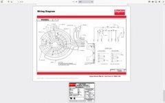
My Dayton motor has 7 wires in the terminal box...red,white,yellow,brown,black,orange and blue. I've already hooked 240v power to it to check operation (both in CCW & CW) and everything is good.
My problem is two-fold:
First I have the usual neutral(white), black(common) and green ground wires from my wall plug. The VFD manual indicates attaching the U V & W wires up and then the ground wire...what 3rd wire is being referred to here that is not the ground? I don't have 3 phase in my shop.
Secondly: I don't have the square "lug block" attachment plate thing on my particular motor. I simply have 7 wires (as previously stated) bunched up in the terminal box on the side of the motor. Is there an easy way to tell which wire goes to what terminal on the VFD? All video's I find show the the VFD being wired up to a motor via the aforementioned lug block.
I know that U V W are European designations but ATO's manual doesn't make any distinctions.
Thank you very much for any/all help.
Bruce Jennings (BIZNAWICH)


