What's new
What's new

Is bolts and electrical tape acceptable for wiring?

MetalArtistCandy

Aluminum
Joined
Jun 1, 2017
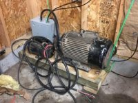
I am building a phase converter. The 20hp motor I purchase has wiring connected with botls, and they used a ton of electrical tale for insulation. I plan to change this from 480v to the 240v as well.


Curious as to other options for crimping the wires together. I did buy some crimp terminals. But I am not sure what crimpers I can use with them. Or if the crimper I have will work.

Split bolts and tape are used all the time for connecting wires, Usually for wires #4 and larger. Basically anything that is too big for the biggest size of wire nut.
 
With bolts, you want to wrap the bolts with that thick rubber padding to prevent cutting through thin tape.
 
Do all 3 phase motors run clock wise looking from fan the pulley the way the diagram shows to connect? I am not sure what will happen when I Apply voltage without a start capacitor. I am using a pony motor to turn the 20hp motor up to speed. But If I apply the voltage to the motor, will it turn slowly in the direction so I know which way to wire the starting motor so I dont spin it reverse of how the electricity wants it to run. Sorry if I cant explain myself. Its easier in my head than when I try to explain it.
 
A 3 phase motor is reversed by switching any two of the three legs. If it is going the wrong way, switch supply 2 wires.
Are you worried the pony motor will turn the idle motor one direction and the it will want to spin the opposite direction when power is applied to it?
 
No need to worry, the idler will spin in the same direction as the pony motor once single phase power is supplied to it.
 
This is how I insulated the bolted connections on my RPC:

It may be overkill but regular electrical tape doesn't seem like a good idea here.
 
Well I f***ed up..

I went to start the converter and POP spark smoke! 😡

When I tightened down a wire clamp it shorted to the power wire.


Well now everything in the box looks like it has some kind of fuzz on it. The wiring, capacitors.

Will cleaning it work fine? I am hoping I can put a different and another clamp on the make them fit without crushing the wire again. I didnt even tighten it very tight, at least that I thought, the screws were not even all the way down.


I have always hated the clamps... i should have done conduit.
 
Well I f***ed up..

I went to start the converter and POP spark smoke! ��

When I tightened down a wire clamp it shorted to the power wire.


Well now everything in the box looks like it has some kind of fuzz on it. The wiring, capacitors.

Will cleaning it work fine? I am hoping I can put a different and another clamp on the make them fit without crushing the wire again. I didnt even tighten it very tight, at least that I thought, the screws were not even all the way down.


I have always hated the clamps... i should have done conduit.

The fuzz is most likely vaporized insulation. Since it is burnt it can be conductive, so clean it off well. Feel the insulation on the rest of the wires to make sure it isn't crumbly. There are two possibilities here: 1) the clamp squeezed two wires together and the only damage will be at the clamp, or 2) The clamp shorted one power wire to ground, which is tied to neutral at the breaker panel. This is the most likely and could also pass significant current through panel wiring. The resulting damage is directly dependent on the upstream overcurrent protection.

Either way, make sure all insulation looks fine, and look at the contactor contacts if you can see them, though they are likely fine. Start and run capacitors can't really be damaged from a short circuit like this.

It should be obvious but you will have to replace or cut out the section of wiring that has been clamped. Romex and similar wire is hard to damage with those clamps. Are you using SOOW wire (oil and water resistant extension cord type wire)? If so you should really be using a different type of strain relief, such as these: https://www.amazon.com/gp/product/B01MDTQAFB
Tightening the nut at the back compresses a rubber bushing which bears down on the wire. Much softer contact, but still very good holding strength.

Also obvious, but are you positive the failure is because of the clamp, and not another wiring issue?

Pictures will help here.
 
Yes, broke insulation right at the clamp, can see the bare copper.

I am thinking about using SO wire. Not sure what the wire type I was using. But now I need to double check alll the rest of the wires and clamps.


Stuff like this just makes me nervous to try and power it up again. Scared of what will happen next.
 
Cool! So it spun up enough to tell ne what diresction it wanted to spin! 👍🏼😃


Ready to install the belt and make my other motor spin that direction.
 
Stuff like this just makes me nervous to try and power it up again. Scared of what will happen next.

Metal Artist -

Well, from my experience you need to just get back on the horse.

Over 40 years ago - I was 27 or so - was building our house. Working one job plus - and trying like crazy to finish the house so we could move in. I had been working the trades since 16 while going through school, etc with a one man general contractor who taught me much and was the lead guy building the house. Sunday afternoon and I'm hooking up circuits in the panel. Thought I was being careful, but in a rush. Managed to short both input lugs while routing a bare ground wire, probably a #12. Vaporized the wire right in my face. I sat down on a cinder block for a minute - scared the crap out of me. After thinking through it I knew I had to route that wire or I might never go into a panel again. Did so, came out fine and tried to continue improving my skills over the years. Luckily the last such experience I have had.

Experience can be a tough teacher. But much better now as far as finding knowledgeable help - this forum for instance - as compared to those days. Just stay away from the 'experts' on the web who are really 'Primitive Pete'. That the line my one brother in law - who before that title was my junior high shop teacher - used to use. You have to be of a certain age to remember the Primitive Pete film strips in junior high shop class.

Dale
 
So I got everything finished this morning.

I and using a motor to spin up to speed,

So the 20hp motor that will be the idler, I measer at just over 3200 rpms

When I shut the pony motor down then apply the 3 phase to the idle motor it buzzes and stops running. On direction it stops immediatly, the other direction it buzzes but doesnt stop all suddenly.


Not sure what my issue here is
I used 22.5 micro farads per hp which is 450 micro farads. I brougt the capacitors from the L1 leg over to the L3 generated leg.

Is there any trouble shooting advice you can help me with?

The first step is to disconnect all capacitors and see if it will run on its own.

My converter does the same thing and I haven't been able to figure it out. There are other things that have gotten other people's converters running though so you aren't totally out of luck.
 
With the breaker turned off, i dont have power to the 3rd leg, but as woon as I tuen the breaker on, I magically have 115 volts on the generated leg, without voltage on the other 2 legs.


There is a contactor that I use to start and stop the voltage to capaictors and
distribution block.

8036BB06-3B96-44F5-9B03-1D3D503BEC47.jpg
 
With the breaker turned off, i dont have power to the 3rd leg, but as woon as I tuen the breaker on, I magically have 115 volts on the generated leg, without voltage on the other 2 legs.


There is a contactor that I use to start and stop the voltage to capaictors and
distribution block.

View attachment 251750

Time to go back and check all the wiring! Get a voltmeter and figure where that power is coming from. All I see is caps and wires in that pic.


Back
Top