Kevin Beitz
Plastic
- Joined
- Mar 10, 2008
- Location
- Pennsylvania
Follow along with the video below to see how to install our site as a web app on your home screen.
Note: This feature may not be available in some browsers.
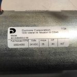
My old fashioned math says 24 volts x 35 amps is 840 va.
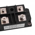
Is it feasible to parallel bridge rectifiers for the purpose of increasing the current capability?
I can buy a 400 amp rectifier for around $20.00 off E-bay. I got the 1000va transformer tral cheap...
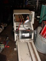
Pictures of the machine, motor,rectifier and transformer that I would like to use.
Notice
This website or its third-party tools process personal data (e.g. browsing data or IP addresses) and use cookies or other identifiers, which are necessary for its functioning and required to achieve the purposes illustrated in the cookie policy. To learn more, please refer to the cookie policy. In case of sale of your personal information, you may opt out by sending us an email via our Contact Us page. To find out more about the categories of personal information collected and the purposes for which such information will be used, please refer to our privacy policy. You accept the use of cookies or other identifiers by closing or dismissing this notice, by scrolling this page, by clicking a link or button or by continuing to browse otherwise.