What's new
What's new

Buck/Boost Transformer sizing

Fish On

Hot Rolled
Joined
Feb 23, 2014
Location
Foley, Alabama
Just moved my shop to a different building. Had 240 single phase and an RPC, new place has 3 phase 208v. Wasn't sure which machines would be happy on 208 and which wouldn't, so (also partially influenced by a lack of time) figured I'd hook them up and see which ones weren't happy. Seems to just be my mechanical shear.

This is a hard starting flywheel driven machine. 5 hp, 230v nameplate rating, 15 amp motor. Fed 240v by RPC at the old shop, it would take a few seconds to spin up to speed, but didn't seem unhappy.

After getting power to it, I blipped the power on for a second to see which way the motor was rotating (wrong of course), so I swapped the 1 and 3 leads, turned power back on, and nothing. Leg 1 fuse was blown.

Purchased a few more fuses, started up the machine and it took quite some time to spin up to speed. 2 - 3 times what it used to, if I'm not mistaken. Shut it down as soon as it was up to speed, and the next time I go to start it, leg 1 fuse is already blown. Not sure at what point in the process the fuse is blowing, but didn't really see the point in burning up another $12 fuse to find out as it's clear it doesn't like 208v.

With just a few minutes left before Mcmaster shipment cutoff time, I did what research on buck boost transformers I could, but certainly did not establish enough of an understanding to be confident in my purchase.

Based on this calculator, it seemed I needed a pair (I'm still not understanding the 2 transformers for 3 phase, but I'm sure they'll come with a wiring diagram) of 500va units.
Buck and Boost Transformer Calculator - Schneider Electric United States

So I bought 2 of these with hopes of being able to install tomorrow when they arrive.
McMaster-Carr

Does it look like I've bought the right units (wall voltage measures 209, motor nameplate is 230. 5 hp, 15 amps. 1.15 service factor motor)? Do these things typically come with instructions/wiring diagrams suitable for someone who doesn't really understand what's going on inside?
 
How large a supply is there to the machine? Is it sized for minimal volt drop during starting?

Thermal overloads should go before fuses.
 
(240-209)*15=465 VA. That's the difference in power that will need to be boosted for each phase at full load. With three phases that comes out to 1395VA of load. Divided by two transformers connected in an open delta configuration, that comes out to 697.5VA of load per transformer - assuming your system is perfectly balanced. 500VA transformers are inadequate for the load to be served. You would need three 500VA transformers in a closed delta, or two 750VA transformers in an open delta. Minimum. Padding an extra 20% above the calculation for tolerance and imbalance is good practice. A pair of 1kVAs would probably do well.

See NEC Article 450.3 for sizing of overcurrent protection.

I'm exhausted as I type this so someone please correct me if I missed something.

Thermal overloads should go before fuses.

Backwards. Fusible disconnects and circuit breakers go on the line side of the controller. That way they can serve as the required disconnect for the controller.

Otherwise you'd have disconnect, controller, fusible disconnect. Or disconnect, controller, circuit breaker.

Not to mention you would have less adequate short circuit/ground fault protection for your control circuit conductors if they are tapped directly off of the power circuit. A current limiting fuse will open much faster and limit incident energy much better than any circuit breaker in the event of e.g. a troubleshooting accident. Enough to turn an arc flash into a mouse fart.
 
And to answer the other question, yes you only require two boost transformers for three phase service. The mcmaster carr catalog actually does a great job of explaining how to size them.
 
(240-209)*15=465 VA. That's the difference in power that will need to be boosted for each phase at full load. With three phases that comes out to 1395VA of load. Divided by two transformers connected in an open delta configuration, that comes out to 697.5VA of load per transformer - assuming your system is perfectly balanced. 500VA transformers are inadequate for the load to be served. You would need three 500VA transformers in a closed delta, or two 750VA transformers in an open delta. Minimum. Padding an extra 20% above the calculation for tolerance and imbalance is good practice. A pair of 1kVAs would probably do well.

Does the fact that my machine is an older one with a nameplate rating of 230 instead of a modern one at 240 change anything, or is there a reason to calculate at 240 regardless?

If I do the same math with 230v, (230-209)*15=315 VA. x 3 phases = 945. Divide by 2 transformers = 472.50.


Additionally, if I follow the sizing instructions on the McMaster online catalog per Jim Rozen's suggestion, it suggests the same units I bought yesterday.
McMaster-Carr

If I start down the menu on the left, select 208v input, 230v output, use the formula VA = Volts × Amps × 1.73 (230 x 15 x 1.73) to get 5969VA, round up to the next available size, it pulls up only the 500VA unit.

But again, that's based on 230 motor nameplate rating, not 240, so it circles back to the same question of is there a reason to calculate at 240 regardless?
 
Well, once they showed up (Acme T181058), the chart in the box showed it was acceptable for a 15 amp load boosting from 208 - 240, so I decided to run with it.

Wired everything up, voltage measures over 240 now, so all is well there, at least until I go to start. Wind up sounds more normal for about 1 second, then it trips the 30 amp breaker in the panel. I guess I'll be pulling new wire and upsizing the breaker.
 
240V is the nominal system voltage. 230V rated loads are typical on 240V systems (115 on 120, 460 on 480, etc.) to allow for voltage drop.

If the transformers are right next to the load, then no, you do not explicitly *need* to boost all the way to 240. Either way most loads will be perfectly happy +/- 10% of their nameplate rating.

Also part of the reason why we allow 20% for tolerance. More voltage applied to the motor -> more current flowing through it.

I should have listened this morning and exchanged these instead of installing them, but I didn't.

Back to blowing leg 1 fuse. Going to order a pair of 1k transformers and start over. It seems that phase 1 blows about 1 second after hitting the start button, but after that, the remaining two phases will get the machine up to speed, albeit more slowly than usual.
 
Have you measured what the voltage is while it starts, and what the locked-rotor current is?

I'm worried that your upstream supply is simply too long and too thin, so you're losing a lot of voltage. This is going to make it take longer to start regardless of what you do with transformers.
 
Seems I've got a new problem here.

After the 500 VA transformers didn't work, I acquired a set of 1000VA units. Installed them, and same problem. Next thing to eliminate was the wire size, based on SomeoneSomewhere's suggestion - increased 2 sizes (from 12 to 8 gauge).

At the last shop, this machine was running fine on 60' run of 12 gauge, fed 240v off a rotary phase converter. At this one, it's now on a 70' run of 8 gauge, with the transformers 20' before the machine, so 50' of 208v, then 20' of 240v, so I'm confident I've got enough wire, even with the lower supply voltage.

After increasing the wire gauge, I started it. Spun up to speed at pretty close to the same speed as usual (maybe slightly slower, but not much). Once it was up to speed, tried cycling it, and nothing - pedal doesn't work. At that point, I hit the off button, and as soon as I did, I noticed the worklight went out, and after checking, find fuse 1 is blown again.

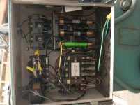
This thing has a 12v worklight, powered by it's own small transformer in the control box. The transformer pulls it's power straight from leg 1 and leg 2, just past the fuses (before the motor starter), so it should always be on when the main power knife switch is on. For some reason, hitting the motor STOP switch is blowing the fuse. Come to think of it, I thinking that happened at least one other time, and possibly multiples - I hope I wasn't chasing a red herring.

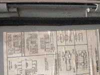
Regardless, now I'm pretty sure I have enough power, so now I need to start figuring out what's going on with the machine itself, to make the pedal not trigger it, and to make the STOP button blow the leg 1 fuse. Nothing looks like it came loose during transport, and this machine was working properly before, so nothing should be hooked up incorrectly.

Anyone have any suggestions on where to start?

IMG_20210615_174509524.jpg

IMG_20210615_174506568.jpg

IMG_20210615_174503912.jpg

IMG_20210615_174459631.jpg

IMG_20210615_174453126.jpg
 
230V 5 HP is about 15A, so 12 ga is fine for reasonable distances. 200V is 17.5A, better to use 10 ga. 60' is, IMO, not reasonable for a hard starting machine, so increasing size is OK. 10 ga would have been OK, most likely, better 8 ga, which you have.

Blowing a main fuse at stop is unusual.

Your controls appear to be on a lower voltage, so they are not directly connected to the mains. If something there got messed up, and there were not fuses in the primary of the control transformer, it could draw extra current when stop is pressed

It is POSSIBLE, maybe, that whatever extra current is drawn , when added to motor current, is enough to blow the main fuse. So if there is a fault in the control wiring, or the stop switch itself, it could cause that problem.

In that case, when the fuse blows, the machine would stop, since current is no longer supplied to close the main relay. So the machine would stop, alright, but not for the reason you expected.

There are supposed to be fuses, or maybe just one, in the control circuit. They SHOULD blow well before the main fuse, but if the control circuit fuse is wrong, bypassed, etc, that might be able to cause the problem.

I do not rate it high as a probability, but it "COULD" cause what you see..... Maybe....... It would be hard on the stop switch, too.
 
Mechanical shock of the contactor letting go could be momentarily completing an intermittent short/ground fault. Or there could be a problem with the power contacts.

Also worth tracing the wires. That wiring doesn't look factory. More like a "maintenance guy/homeowner special". Wouldn't be surprised to find the previous owner effed it up.

Follow your nose. Look for burn marks. Check control fuse, make sure it is sized correctly. If control circuit secondary is fused correctly then it is unlikely the fault lies in the control wiring unless previous owner cross-circuited. Check for short/ground fault in control circuit with stop button pressed. Also check for short/ground fault in power wiring with stop button pressed. You never know what 'brilliant' ideas the last guy came up with.

Be smart and follow your gut.


Also see NEC 450.3 for transformer overcurrent protection sizing.
 
I'll do some more tracing when I go in today. Everything I traced last night seemed correct to the diagram, but I've learned a bit more about motor starters overnight, so I'll see what I can trace.

This machine did run for almost 2 years in my last location, and I've changed nothing with the wiring, so it stands to reason that the problem was either caused by transport, or my supplying it with lower voltage initially.
 
That is the sort of fault I was thinking of. wires that came loose, rubbed through insulation, etc.

We're back in business, and that's exactly what it was. Seems the rigger managed to pinch the flexible metallic conduit going from the starter to the motor, and damaged one of the wires inside. It's where it wraps underneath the gearbox, so you can't hardly see the pinched spot without laying on the ground. I've replaced the factory 12 gauge wires in that with new 10 gauge ones, and we're back in business.

Odd that it blew the fuse only during shutdown. I had been worried for the past couple months leading up to this move that this machine and one other I've got wouldn't be happy on 208v, so when it started blowing fuses, that sure seemed like the obvious approach, but definitely a red herring that got the best of me.

On the upshot, the shear spins up to speed faster than it ever has before, so it's definitely happier with it's current setup of transformers and 8 gauge than it was on an RPC and 12 gauge, however I'm left wondering how much of that was actually necessary - would it have been okay on 208v, or with just the smaller transformers - but that doesn't much matter at this point.


Back
Top