What's new
What's new

Bypassing the timer PCB on American Rotary 40hp panel

Fear624

Plastic
Joined
Oct 31, 2019
I've got an old American Rotary panel. The previous owner got plenty of use out of it since he got it back in 2014. But then it blew most of the start caps and he talked to American Rotary, they talked him into a newer panel so he passed this panel to me. I made a frame around the panel and a new 40hp Baldor motor and wired it per Baldors instructions with new caps spec like the originals with same value resistors soldered on as original.
When I hit the start it just hums really loud like it's overloaded and the shaft twitches back and forth. I hit stop, spin the shaft by hand and hit start and it speeds up a little but still sounds way overloaded and doesn't speed up.
American Rotary is no help at this point. They don't have schematics on a unit this old and just want to sell me a new panel. I've torn the panel part way down and inspected and mapped everything. It seems it comes down to a bad start contactor or a bad PCB timer board.
I'm just thinking of eliminating the PCB. I can remember to not hold he start button down too long.
Power comes from L2 1ph through the NC stop switch to the white wire in one side of the three run contactors as well as the NO start button leading to the black wire to the timer board. The timer board has a white wire to trigger the start contractor and a black wire leading to the opposite side of all three run contactors from the white wires.
The remaining wires off the PCB go to L1 1ph (BK), T2 (RD), and the T3 fake leg(BL).
The rest is straight forward. Run contactors close the L1 1ph to T1 3ph and L2 1ph to T2 3ph. The Start just closes from caps energized off of T1 3ph to T3 fake leg and theres some run caps between T2 and T3.
The contactors are Schneider LC1K091OU7 start (still a good number) and LC1DT40 run (x3)(not a current number, I think it's superseded by LC1DT40U7 but need to call Schneider to know for sure.)
I'm thinking I could just add a second NO momentary sw start button from the NC stop switch to the white wire to the start contactor.
I just don't know if the PCB has step-down transformer for lower voltages/currents for controlling the contactors or latching relay-qualities to work with the momentary start button so those would be issues before i straight-up remove the timer PCB.

I'm sure someone has bypassed the timer board before.
 
I'm sure someone has bypassed the timer board before.

"I'm sure.." that as you have nada from the OEM, and they don't "owe you" any, either? You'd be better-served working with info that you CAN get and doing it "their way":

Three of the best and most well-proven designs are linked to "Right here, on PM". already:

Rotary Phase Converter Designs and Plans

"Scale" the values to your ider's HP, any of those should JF work.

Mind .. starting a 40-hoss idler off caps? I wouldn't even think about that with my paltry residential service.

10 HP I DO. Phase-Craft controller.

But even at 20 HP and up, and 40 HP for-damned-sure, I'd "pony" start. 12 or 24 VDC off batteries in my case, 'coz I already have them, and on "float" charge to spin-up the ex-NATO Diesel gen set.

Otherwise, "inrush" at start is a right bitch, and not all premises can support it, good RPC starter/controller... or not.

2CW
 
I ran 400amp service to the shop. Per American Rotary, I have a 125a breaker feeding 3-0 cables for input. They make RPCs bigger than my 40hp and the previous owner was running a huge 3ph compressor off of it for years.
I was trying to apply a Fitch RPC plans to it, but it's a way different design with cheaper contactors. I'm not going to toss a bunch of $260 contactors to match someone's cheaper RPC design.

You still aren't "getting it", then.

You don't "toss them". You re-purpose the best goods out of what you have - contactors included.

What Fitch gave us- given power systems for spacecraft & rockets was his "Day Job" and he "knew the maths" - and gave us in 10 HP, IIRC, because it "scales" really easily - is the HOW of what does what, with which, and to whom.

Higher-grade components are higher-grade components.

American Rotary hasn't even been able (or willing) to provide a schematic of what THEY built? And why would they? You were/are not their customer. Same economic position as any other dumpster-diver. "Bypassing the timer PCB" brands you a potential liability risk. Not an asset.

How useful has THAT been, so far?

And oh, BTW".. "waay different" as applied to 1-P to 3-P RPC?

That's akin to comparing health insurance plans for common single-wheel wheelbarrow clans and tribes. The barrows. Not the operators.

There ain't but a limited number of ways to BE "different". Or not so much.
 
I think I have it.

There's no sense in re-engineering the whole car if the glovebox is the only problem.

The engineering and sizing has already been done, I just simply have to replace a PCB with a simple button.
There's no schematic breakdown on the Schneider contactors to keep a simpleton like me amused. I keep thinking of them as big relays but I think there's more to it.
On the D-line run contactor you apply each leg of 240v 1ph to A1 and A2 respectively and it closes the contacts. I think, by the way they wired it, if you apply momentary power to A2 with a jumper to 14NO with the other leg applying power to 13NO from a NC kill switch it will latch with the button and terminate when you open the kill switch.
It's already got the run contactors wired that way around the timer board. I don't think removing the timer will affect kicking the run contactors in and out.
I just need to run a wire spliced to the kill to a momentary button and then to the K-line start contactor A1 and A2 is already hooked to T1 3ph so when the run contactors break, there won't be any way to energize the start contactor.
If I do that I can just remove the timer board completely.
 
I think I have it.
.
.
If I do that I can just remove the timer board completely.

"Less risk of drama" approach, then:

- first, confirm your contactor(s) do what you expect by running only enough power to satisfy the actuating coil(s).

I have found a PAIR of two-dollar dirt-common Medium Edison base (ignorant incandescent lamp socket) wired in the "test" line handy. "Test" line is an outlet on my"test bench" fed off a mere 15A Square-D "QO" panel breaker to a ISTR 10A breaker in a(ny) good grade of power "bar" for the 1XX VAC items. There's a 20A Variac on the bench as well.

2XX VAC, run instead to the lamp sockets, then the item under test. Optionally, grab a selection of screw-in "mini-breaker" in several ratings.

Also some incandescent lamps to serve as current-limiter / Voltage droppers.
Half-assed ones, as the cold/warm value changes a LOT, but still - they also serve as warning lights to remind you that power is ON and being f**ked-around with.

Less "dramatic" than flipping 80A into the Mike Foxtrot live rig at full-gallop... only to find you triple-checked... and still got ONE damned wire DEAD WRONG!

DAMHIKT!

:D
 
Contactors are simply relays, with high current ratings.

Depending on the part numbers of the contactors, they likely have a comination of normally-open and normally closed poles. You probably won't find a changeover contact. You might also find that some poles have a different current rating to others, e.g. three large NO contacts for a motor, and a small NO and NC contact for control circuitry.

The only exception is if you have a mechanically interlocked contactor.

It sounds like you're pretty much there; you might find it helpful to draw a diagram and go look at direct-on-line starter diagrams.
 
Contactors are simply relays, with high current ratings.
They (often) have similar functions, but no - there are other distinctions. Some "power relays" are waaaaay larger than some "contactors", for example.

More to it than semantics, given that about 80% of the easily-found published sources miss the most important differences and grab something "easy" but not necessarily correct.

eg: It is NOT JUST the contact form, voltage, current carrying capacity, AC vs DC, phase-count, nor frequency of operation.

Not that it needs a lot of discussion.

One ordinarily BUYS tested and proven goods and applies them. "Code" and and/or insurers & inspectors-of same generally require that. And it makes good sense.

Inventing / designing / building yer own, OTOH, takes a bit more care!

:D
 
That's fair, but I'm curious what your definition is. I can think of counter-examples I've used to just about every definition in lists I've found. E.g. normally closed contactors for some lighting & emergency applications, high-power relays as you say, double-break relays where you really want it to break the connection, and that's before we start talking about SSRs.

I can only come up with "that's what the manufacturer calls them".

Code is all well and good, but (at least here) it doesn't generally care about the difference between the two as long as it's rated to break the load.
 
....as long as it's rated to break the load.

Bingo.

Well.. "flow of power"? We'd like the "load" to be more than single-use?

:)

"Prime directive" for a(ny) "contactor" is that it can ever and always reliably BREAK the circuit. Failure is not an option.

Failure to "make" OTOH? Generally "fail SAFE".

THIS.. is what drives the materials selected, their shape, the mounting method (springs, even..) the contact form, the preference that the action mechanism remain isolated / not (yet) involved in contact with the power UNTIL it is moved into "bridging" action between other contacts.

The "contactor" function, IOW. Just as it says it is.

That contacts have shaping for successful arc management, each time, every time, use of "blowout" coils, LOCALLY present "thermal" breakers or equivalent, placement of the device CLOSE to the controlled load, and other details all of which support that...

... life, money or other "important safety stuff" MUST be served by ability to "BREAK" come Hell, high water, or Hong Kong harbour freezing clear to the bottom.

Contactors generally operate as "locally" to the controlled load as can be made convenient. "Best of intentions" and damned-good "practices" as to always being able to "BREAK", fail can still happen, remedial action is not meant to need a long drive by motorcar, so lengths of dry timber, insulated hammers and fire axes might exist, and close to hand.

A "relay" does what it says it does, also.

"Re lays" control information - simple or complex - to a REMOTE device.

"information" CAN be "You are powered ON, now Sir Load!" But that's only one subset.

"Remote" can be in the same housing.. or as much as 8,000 unrepeatered miles "remote", same wire, the Australia - Hawaii submarine telegraph cable and @ 8,000 volts, DC - whichever end was sending, "simplex" mode by time schedule.

Surely not your average telegraph key, yet neither did it class as a "contactor".

So a relay has a different "prime directive".

Any and all modes it "owns" are equally important. No bias toward "fail-open is safe".

Can't even tell in advance which mode IS "open", nor '"safe", nor even if it is involved in power transfer, mode selection, or signalling, only.

Have a look at a "hook switch" in old rotary-dial telephones. Lot of "stuff" goes on when yah move the simple hook or button. Lot of relays are easily as complex. See also "T-bar" relays.

See TTY relay, vacuum, "reed". Also "mercury wetted" cousins.

Claim to fame?

How many cycles they had to live through to be of any use in their job.

Reliable "cycles". As with "contactors"..... just insanely higher numbers...

Mind.. I'm partial to Mercury-Displacement "contactors", soo... live long.. or die with a lot of messy drama! Not a type yah want to see overloaded.

Nor operated where UP and DOWN are not firmly preserved!

Springs can fail. Gravity?

Not OFTEN... but the Loma Prieta quake surely got MY attention, so it probably played B***dy Hell with any Mercury displacement relays or contactors in the zone!

:D
 
IMG_1085.jpg

As long as I have the latch to reset in the event of a power interruption, I'm happy. Nothing explained (in away my dumb ass could comprehend) that completing a circuit through A1 and A2 closes the 4 sets of contacts in the bottom. Then there's two sets of low-amp control circuits for optional that change with the energized contacts. A NO circuit and a NC circuit. You apply L1 to one side of A1/A2 and then apply L2 to that same side of the NO circuit. and then put a jumper from the unused side NO to the unused A1/A2. You now have full power available in a static off sense. Now a quick zap to the side with the jumpers from L2 closes the contacts as well as the NO and the contacts stay closed, thanks to the NO circuit. It holds this way until there's a momentary break in the L2 and everything springs apart into the static off status. What I consider like a latching relay from an old VW Beetle high-beam switch.
That's all I needed where a momentary NC supply can be triggered for half a second and everything goes dead with no risk to contactors or caps. A simple stab of a NO start switch to energize the run contactors and a second stab at a NO switch to trigger the start contactors and we're in business. Safe, simple, tidy.
 
"Prime directive" for a(ny) "contactor" is that it can ever and always reliably BREAK the circuit. Failure is not an option.

Failure to "make" OTOH? Generally "fail SAFE".

THIS.. is what drives the materials selected, their shape, the mounting method (springs, even..) the contact form, the preference that the action mechanism remain isolated / not (yet) involved in contact with the power UNTIL it is moved into "bridging" action between other contacts.

The "contactor" function, IOW. Just as it says it is.
Well, yes. Things that are designed for a specific purpose use materials and construction suitable for that purpose.


That contacts have shaping for successful arc management, each time, every time, use of "blowout" coils, LOCALLY present "thermal" breakers or equivalent, placement of the device CLOSE to the controlled load, and other details all of which support that...

... life, money or other "important safety stuff" MUST be served by ability to "BREAK" come Hell, high water, or Hong Kong harbour freezing clear to the bottom.

Contactors generally operate as "locally" to the controlled load as can be made convenient. "Best of intentions" and damned-good "practices" as to always being able to "BREAK", fail can still happen, remedial action is not meant to need a long drive by motorcar, so lengths of dry timber, insulated hammers and fire axes might exist, and close to hand.
Some of those functions would be better served by a circuit breaker with a shunt trip or undervoltage release. It's certainly worth having local isolators and main switches in case the control system goes nuts.


A "relay" does what it says it does, also.

"Re lays" control information - simple or complex - to a REMOTE device.

"information" CAN be "You are powered ON, now Sir Load!" But that's only one subset.

"Remote" can be in the same housing.. or as much as 8,000 unrepeatered miles "remote", same wire, the Australia - Hawaii submarine telegraph cable and @ 8,000 volts, DC - whichever end was sending, "simplex" mode by time schedule.

Surely not your average telegraph key, yet neither did it class as a "contactor".

So a relay has a different "prime directive".

Any and all modes it "owns" are equally important. No bias toward "fail-open is safe".

Can't even tell in advance which mode IS "open", nor '"safe", nor even if it is involved in power transfer, mode selection, or signalling, only.

Have a look at a "hook switch" in old rotary-dial telephones. Lot of "stuff" goes on when yah move the simple hook or button. Lot of relays are easily as complex. See also "T-bar" relays.

See TTY relay, vacuum, "reed". Also "mercury wetted" cousins.
Yes, but as previously discussed, power relays. E.g. an Omron G7L, with double break contacts with a large gap. Versus using something like an ABB ESB to switch some office lights.
 
Some of those functions would be better served by a circuit breaker with a shunt trip or undervoltage release. It's certainly worth having local isolators and main switches in case the control system goes nuts.
Well it ain't one of Hydro Quebec's puppies, so I'm good "upline" with Square-D QO, 3-pole, common-trip, then an "on machine" lock-outable 3-P "rotary" disconnect, front of the lathe, TS end. Basic "starter" after that nless DC Drive where the drives have the functionality inbuilt / optioned active.

Good place so an operator's right hand can use the disconnect "in an emergency" instead of walking around to the back of the machine, close to the wall, where most OEM ones were hung.

Upstream of that, SO cord to a Hubbell twist-lock.

Not all that different, the RPC and Phase-Perfect incoming single-phase feed. Hubbell and a decent disconnect as well as their Square-D "QO" 2-pole-common-trip breakers.

Yes, but as previously discussed, power relays...
"Just for the Halibut", as long-term, BOTH of my own 10EE will have 4Q SSD power and NO mechanical contactors, I've been looking at replicating the "DC panel" functionality with 100% current-production components.

Gigavac HX series caught my eye to replace the 10EE's heavy 1930's technology contactors.

Overkill? Just a tad!

High Voltage Contactors - HX Series

But that's why the OEM ones can last what looks to be a hundred years or more. And the Gigavac's aren't bulky, nor all that costly.

If they are "nice enough", I might even replace my Mercury-Displacement contactors for the RPC primary & supplemental idlers.

I'm au fait with those.

Also no longer young. Next minder might be better-off to NOT have Hg in the rig?

:D
 
Yeah, the rotary disconnect is what I meant. I tend to deal with stuff where we have an isolator per motor, rather than per machine.

Breakers don't have to be used solely as breakers. Larger transfer switches usually use motor-operated ACBs as it avoids the standby losses of a multi-hundred-amp contactor, and has better breaking capacity.

In a whole-plant fire shutdown situation, a shunt trip on a large MCCB or ACB is likely to be a far better than a contactor.

Using a CB also ensures that you can't weld the contacts by closing into a short circuit - this can happen more easily on contactors.

Unfortunately US gear is a lot less amenable to expansion and accessories than DIN stuff.
 
Unfortunately US gear is a lot less amenable to expansion and accessories than DIN stuff.

Aye. Thankfully. Good reason to plan better and get it right the FIRST go, yah?

:)

ROYAL f**king Pain In The ASS that fragile under-engineered AND overpriced DIN-mount Euro-shite.

Thankfully only had to be f**ked-over by it briefly before telecoms went over to time-division, then packet and needed less complex power management!

I've been having to strip DIN-shite out of my Cazeneuve HBX-360-BC and replace it with sturdier US made bulkhead-mount bolt-ons.

DIN rails are handy for cable management clamps and DIY toolholder racks, though!

US translation of "Deutsches Institut für Normung"

"Ben Dover!!!".

:D
 
I bypassed the timer board and tried it with a second NO button going straight to the start contactor and reassembled it. Now I hit the button that engages the run contactors and then hit the button for the start contactor and the shaft won't spin on it's own, just sits and twitches back and forth.
I try again by spinning the motor output shaft by hand and then hitting the run contactors and then the start contactor. As long as I hold down the button on the start contactor, the motor sounds good and speeds up. But as soon as I let go it slows back down and hums very loud. I let it hum too loud for a few seconds while trying to read the phase data and it popped the single phase 125amp breaker.
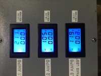
The next time I got my wife to get a few snapshots of the three-phase data before I hit the kill.
There's over 240v input.

PhaseReadingsThreePhaseRPC.jpg

SinglePhaseInputVoltageRPC.jpg
 
I bypassed the timer board and tried it with a second NO button going straight to the start contactor and reassembled it. Now I hit the button that engages the run contactors and then hit the button for the start contactor and the shaft won't spin on it's own, just sits and twitches back and forth.
I try again by spinning the motor output shaft by hand and then hitting the run contactors and then the start contactor. As long as I hold down the button on the start contactor, the motor sounds good and speeds up. But as soon as I let go it slows back down and hums very loud. I let it hum too loud for a few seconds while trying to read the phase data and it popped the single phase 125amp breaker.
The next time I got my wife to get a few snapshots of the three-phase data before I hit the kill.
There's over 240v input.

View attachment 288536

View attachment 288540

Look again at the Fitch Williams diagram. It covers all the "basic bases" for cap start, calculated cap values, and switching sequence. Cap values are not all that critical, BTW. Their relative ratios more so, but not "show stoppers", even then.

It's a "forgiving" circuit.

Try to duplicate that out of the parts you have to-hand and already "paid for", yah might not have to spend a lotta time, nor a single extra dime.

Keep-on trying to go half maker's OEM, but no drawings, half guesswork monkey-patch or some other percentage mix so you hope to have LESS labour?

Similar to re-inventing the wheel as a hybrid after the PREVIOUS guy - the OEM - already started on it from some other direction... wastes yer time. Annoys the pigs and grownups alike. So why wuddja?
 
Aye. Thankfully. Good reason to plan better and get it right the FIRST go, yah?

:)

ROYAL f**king Pain In The ASS that fragile under-engineered AND overpriced DIN-mount Euro-shite.

Thankfully only had to be f**ked-over by it briefly before telecoms went over to time-division, then packet and needed less complex power management!

I've been having to strip DIN-shite out of my Cazeneuve HBX-360-BC and replace it with sturdier US made bulkhead-mount bolt-ons.

DIN rails are handy for cable management clamps and DIY toolholder racks, though!

US translation of "Deutsches Institut für Normung"

"Ben Dover!!!".

:D

We have a fair number of boards around here built with Westinghouse Quicklag breakers. They are what is now US Eaton type QC. They're awful boards, with poor terminals, loads of exposed busbars etc. I don't think I've seen any without at least one terminal that looks toasty, and they're known for breakers that get 'weak', as well as occasional failure to trip.

We have an order of magnitude more Merlin Gerin C60, similar age. And an order of magnitude fewer faults with them.

Accessories aren't to fix a previous fuckup. They're to let you do things you couldn't otherwise.

We can get basic GE MCBs for <$5/pole and the nicer commercial ones for <$10.
 
Keep-on trying to go half maker's OEM, but no drawings, half guesswork monkey-patch or some other percentage mix so you hope to have LESS labour?
?

I don't get this, sorry. First order of business when trying to unwind some botched engineering fuckup from a company that relies on "proprietary" aspects of their
stuff to make money, is to reverse engineer the entire thing. And the first part of the first order of business is to generate a complete and accurate schematic
diagram of the fuckup in question. Typically this means two or three versions of the diagram, each one getting closer and closer to a sensible signal flow layout.

Without that the re-work is just a shot in the dark and has a less than even chance of working.

I have an entire folder here at home that is devoted to re-engineer projects.
 
I've drawn out a schematic. Actually it's split across a dozen sheets of paper.
2 run caps running between T2&T3(fake leg)
5 run caps running between T1&T3(fake leg)
4 start caps running between T1 and the start contactor then to T3(fake leg)

The control is pretty much the way I drew the run contactor, just 2 more run contactors run with the control circuits running in parallel off the first contactor and a wire running off the NC stop switch to a second NO momentary start switch then to A1 on the start contactor with A2 going to T3.

It's about as simple as it gets after removing the timer board. No transformer or internal fuse like the Fitch design because the more expensive contactors allow a 240v control circuit.


Back
Top