All that love you showed the W & S, but no attention to the motor or controls, hurts my eyes.
-Apologies. Electrics aren't my strong suit. They're not even an old hand-me-down suit in the back of the closet I haven't worn in twelve years.

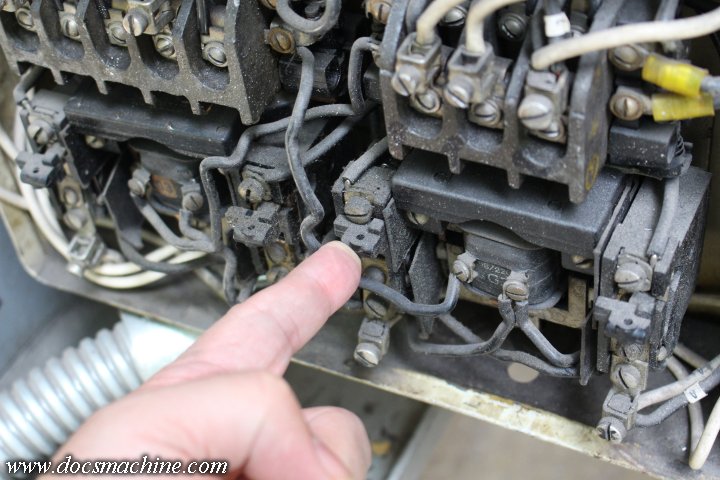
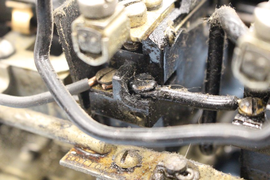
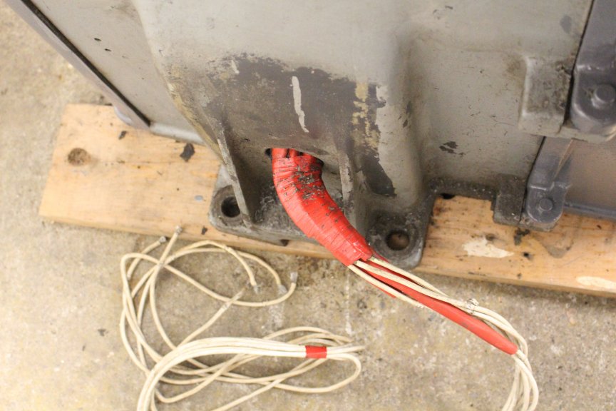
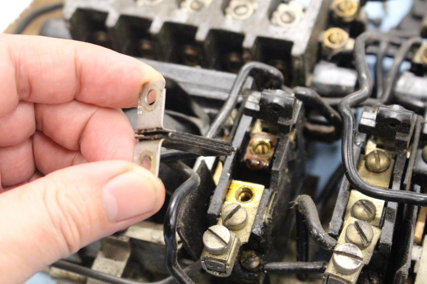
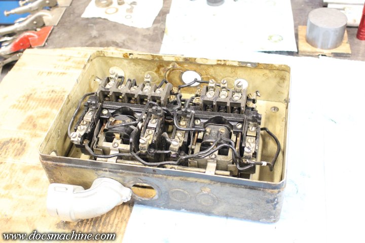
Yes, I'm admittedly taking a bit of a risk with the original contactors- they DID work when I tested it, and I'm kind of hoping that the issue with the resets is due to being fed a 'dead leg' from a cheap static converter. Or the one broken wire in there. Or both.
I've since upgraded to a better rotary/
You could likely replace the entire controller easier than finding a cover or making one for that obsolete starter.
-This isn't the only place I've asked around on, and unsurprisingly, no one's had a lead. I really wasn't expecting it to still be in production, but I did kind of hope I'd find somebody who had a stash of old parts out back.
Anyway, I've since ordered an entire new enclosure, slightly larger, from McMaster.
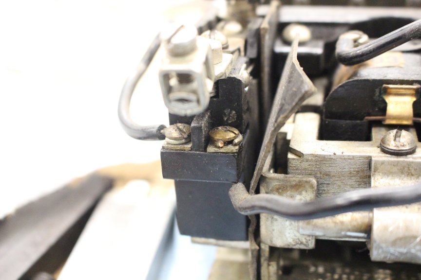
From your pictures it looks as though it has a problem already, and finding parts for it will be futile.
-Fully agreed. If one or both of these fail, or still don't work even when properly wired and fed proper 3-phase, then yes, I'll be more than happy to replace them.
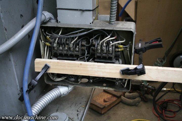
From the pictures it appears as a two speed starter, due to the fact that it has two separate overload relays.
-Yes, it's a two-speed motor. 2-1/2HP/700 RPM and 5HP/1400 RPM. I'm told it's an either/or system, one winding OR the other, but not both. There's a sort of "balance bar" in there at the bottom, that prevents one contactor from operating if the other is already engaged.
Hoffman 18" x 18" x 6" Type 3R Screw Cover Box, Galvanized Steel
-On issue is that I'm kind of tight on space. By necessity, I have to put the machine in the corner and up against a wall. Much larger than the original size will start causing issues, so I tried to get one as close as possible. The McMaster one is 2" taller and 2-1/2" wider, which is pretty much the best I could find.
Two speed starters are a bit more rare today, but they can be found with a bit of pecking.
An ideal one would be a combination type factory mounted in it's enclosure with a disconnect. Here is an example of one that may be suitable for you for a fair price with current model starters.
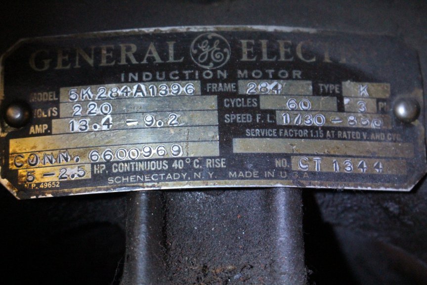
-I may very well end up needing that. Assuming it will work with my setup. Apart from the info above, it's 230V, and I think a max of 13-point-something amps at high speed.
[edit] And no, I don't need electrical reversing. Reverse is handled in the headstock gearing.
I made some assumptions based on experience, but to pick something correct you really need some data on your motor. HP, motor tag info, voltage, winding type. I assume that yours is a two independent winding type winding, based on your starters and pusbutton station.
-Yes, that's what I'm given to understand. I would not mind a bit replacing these, it's not like I need to keep it Concours original.
This is very much going to be a working machine, so having reliable power is important.
Doc.
")