M. Moore
Titanium
- Joined
- Jun 8, 2007
- Location
- Vancouver Island, B.C. Canada
Slightly off topic but hopefully I can get some help here.
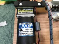
The pic shows the circuit board from my massage bed, an essential tool to keep me working!
It is a Ceragem.
The control is beeping and then showing a code, OD, which means motor overload according to the manual.
I am no electronics expert but I did check the voltage going to the motor and it is showing only 12 volts. Motor name plate says 1.4 amps and 24 volts.
The power supply puts out 5,13 and 24 volts and those voltages are incoming correctly measured at the connection just to the left of the motor wires. However the 24 volt wires are showing 29 volts, not sure if this matters. Low voltages are right on 5 and 13.
So what to check? Simple fix?
Thanks in advance for any help.
Michael