What's new
What's new

Control transformer/x2 terminal on starter question

DeSelle

Cast Iron
Joined
Oct 23, 2006
Location
Midlothian, TX
Hi all,

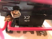
I’ve been working away on my RPC and I have a question about the wiring for the control circuit. I have scanned everything I can find and watched a bunch of videos but this is eluding me. The transformer I have is 240 to 120 and my coils are 120 so that is ok. The outputs on the transformer are X1 and X2. The coils both have 2 terminals. Both motor starters also have an X2 terminal and I read somewhere about connecting the X2 Contactor and transformer terminals to ground and then one side of each coil ( I have two contactors) to ground also then switching the X1 terminal to the other coils to control them. Is this correct? In testing it it works with just running the wires from the transformer to the coil and switching one but is that correct? Or should I be connecting (bonding?) the X2’s all together and to ground?

Thanks for any help as always,

I hope to wrap this up this weekend and post pics so you all can provide the much needed constructive criticism.....

Thanks,

Nathan
 
Is this what you mean? I would rather do his when the control transformer is 24VAC.
 

Attachments

  • THE-CONTROL-TRANSFORMER-0608_thumb.jpg
    THE-CONTROL-TRANSFORMER-0608_thumb.jpg
    37.4 KB · Views: 924
Hi Ron’s,

That’s actually the image that lured me down this rabbit hole. It answers half of my question. So I ground one side of the control transformer output. Sounds like X2 from what I have read. But then there are the X2 terminals on both my starters. Do they ground also? And one side of each of their coils? Ground? All these to the same ground as the machines? I have a ground strip mounted to the metal plate that all the components are mounted to that carries the ground wire from the idler, the lathe, and the ground back to the panel.

Thanks for the response, I’m sure it’s a simple answer I’m just not asking the question right.

What part of California?

Nathan
 

Attachments

  • ECE0D36E-495B-4416-9EC0-7962E2B36B5D.jpg
    ECE0D36E-495B-4416-9EC0-7962E2B36B5D.jpg
    13.3 KB · Views: 224
  • 4F16FB2E-CED7-4129-91CC-4EBBFA4A4377.jpg
    4F16FB2E-CED7-4129-91CC-4EBBFA4A4377.jpg
    12.2 KB · Views: 339
  • 8B7995B8-AF8E-488D-97B0-E03B8B260E32.jpg
    8B7995B8-AF8E-488D-97B0-E03B8B260E32.jpg
    13.8 KB · Views: 204
Grounding just turns that terminal into the "neutral". Just ground one place, and run wires for that connection (the neutral) just as normal (and as the diagram shows).

It's really just a safety measure, so primary to secondary shorts do not make everything live at primary voltage.
 
If you are going to ground one side of the control transformer then you have to ground one side of your starter coils. If the labels say X1 and X2 on the starter coils then use X2. One of my starters has the labels A1 and A2. Another one has V and W. I could care less. Be consistent if you can. And the control transformers I use have a fuse block on top. I avoid high voltage controls and always use 24VAC for safety reasons.
 
If you are going to ground one side of the control transformer then you have to ground one side of your starter coils. If the labels say X1 and X2 on the starter coils then use X2. One of my starters has the labels A1 and A2. Another one has V and W. I could care less. Be consistent if you can. And the control transformers I use have a fuse block on top. I avoid high voltage controls and always use 24VAC for safety reasons.

Sorry, but you would NOT ground all of your X2 terminals (if I am reading that correctly). You can only ground the X2 terminal at the transformer, which establishes it as a "grounded neutral", but from that point on that neutral is a "current carrying conductor" so it must be insulated wire, with (conventionally) white insulation. It would tie to the other X2 terminals on the OL relay blocks IF those are the last terminals after the OL aux contact that drops out the coil (but you didn't post enough of a picture to tell) and THEY might be run in red inside of the starter, but YOUR wire must be white to signify that it is a grounded conductor. If you were to ground the other X2 terminals in the starter, you are turning your entire back panel into a current carrying conductor.
 
Sorry, but you would NOT ground all of your X2 terminals (if I am reading that correctly). You can only ground the X2 terminal at the transformer, which establishes it as a "grounded neutral", but from that point on that neutral is a "current carrying conductor" so it must be insulated wire, with (conventionally) white insulation. It would tie to the other X2 terminals on the OL relay blocks IF those are the last terminals after the OL aux contact that drops out the coil (but you didn't post enough of a picture to tell) and THEY might be run in red inside of the starter, but YOUR wire must be white to signify that it is a grounded conductor. If you were to ground the other X2 terminals in the starter, you are turning your entire back panel into a current carrying conductor.

Good call on that. I am using 24VAC in one installation and do use the back panel. For a long time. I may change that.
 
Ok I’ll change that. As it is, I have grounded the X2 on the transformer and the X2’s on both contactors and one side of each coil. I’ll remove the X2 from the contactors then should be ok?

I agree 24 volts would be nice but all of my components were free and I believe 110 control voltage can be safe if I do it right. Big if.

I have high voltage contactors and transformers as well but obviously would not want to use them for this.

I would still like to know what the X2 connection on the contactors is for. They make a big point of labeling it. Almost more so than any other terminal on the thing

Nathan
 
Hi Ron’s,

That’s actually the image that lured me down this rabbit hole. It answers half of my question. So I ground one side of the control transformer output. Sounds like X2 from what I have read. But then there are the X2 terminals on both my starters. Do they ground also? And one side of each of their coils? Ground? All these to the same ground as the machines? I have a ground strip mounted to the metal plate that all the components are mounted to that carries the ground wire from the idler, the lathe, and the ground back to the panel.

Thanks for the response, I’m sure it’s a simple answer I’m just not asking the question right.

What part of California?

Nathan

Picture #3: Do you know what a overload relay is and does? Is that a BA13A part number? It looks like the X2 is on your overload relay. In the picture it is written as three "OL"'s in series. The X2 connection would be on the right side.

List the part number for the contactor. The overload relay is a different part and can be detached.
 

Attachments

  • THE-CONTROL-TRANSFORMER-0608_thumb.jpg
    THE-CONTROL-TRANSFORMER-0608_thumb.jpg
    37.4 KB · Views: 106
I read about them. If I understand it they open under over current and remove power from the coil


Sent from my iPhone using Tapatalk Pro
 
You understand right.

Is the X2 label on the overload relay. If so then post #10 answers your question. Otherwise list your full part numbers for the contactor and overload relay.
 
That I’m not sure. I only have a very basic knowledge of these starters.
ff3d6339399a51256c01828ecc21a2fd.jpg
8a9fcf694bb2a6f61959c2f6a3f3b57d.jpg


Sent from my iPhone using Tapatalk Pro
 
1. Ok, I have the same style motor starter as your Cutler-Hammer. Mine is labelled GE but it looks like a duplicate. On the overload relay there is a "X2" on the top screw. The screw below X2 is the other side of the overload contact. A similar arrangement is on the Square D. So post #9 is correct. The X2 is just one side of the NC contact. You do not need the overload relay on the Cutler-Hammer because you are just switching a bank of start capacitors for a short period of time. It should be removed.

2. The Square D overload relay is going to protect your RPC idler. A free motor starter is nice to have but the heaters in the overload relay may have to be changed.

3. I route the idler motor T3 through the motor starter (your Square D). Most people don't work it that way. I think your are using a massive effort to connect your start capacitors with that Cutler Hammer. Can't you use something smaller and save that motor starter for something else, like maybe a backup part?
 
Last edited:
Thanks Rons

I checked the heaters this morning. They are B25’s rated for 16.6A and my 7.5HP idler would say that I need the B36 heaters for 21 amps. I guess I can try them and worst case the open and I have to upsize. From what I read most people’s idlers pull very little current after the inrush.

As for the cutler hammer, I don’t know how else to switch the caps in and out? The Fitch diagram I am going off of shows a contact set for them. I welcome ideas? I have a pile of old starters that’s why I chose that. I have a few relays as well but they are 10-15 amps and I don’t know how many amps I should prepare for with 500-600 mfd of start capacitance

Again I welcome any advice

Thanks


Sent from my iPhone using Tapatalk Pro
 
You should at least not use the X1/X2 connections for the overload relay on the Cutler-Hammer. Remove those wires because it make no sense to use that function. The will simplify the wiring. You can leave the heater block on the Cutler-Hammer if you like the way it looks.

If you are going to have push button switches like those AB's then look at the picture in post #2. Underneath the start switch there is a auxiliary contact which is coupled to the main contactor, that would be your Square D. I don't see any auxiliary switches on it. Unless you are planning to use the L3/T3 set of points. I would use a small auxiliary contact and route the T3 of the idler through the L3/T3 set of points.

The Fitch diagram is not gold you know...
 
Thanks Rons

I may take the heater block off if I can figure out how. Do you know how many amps I should plan for from the caps? I have a couple of 30 amp relays I could use but the they are exposed contacts


Sent from my iPhone using Tapatalk Pro
 
Thanks Rons

I may take the heater block off if I can figure out how. Do you know how many amps I should plan for from the caps? I have a couple of 30 amp relays I could use but the they are exposed contacts


Sent from my iPhone using Tapatalk Pro

I have used that type of relay in a 5hp RPC. I used energy absorbing devices across the two sets of contacts. But you get the clicking sound of a relay. Somewhere on the website I posted a picture of a RPC I built 15 years back.

I have a new high current mercury wetted relay. This relay makes just a barely audible noise then is quiet. It will last a long time.


Struthers-Dunn - M6A-24DC - 24/28AC/DC Vol-Rtg 12 Ctrl-V 24DC Cur-Rtg 6A 1 NO Power Mercury Relay - Allied Electronics & Automation
 
Last edited:


Back
Top