The voltage you read across the center coil, is a function of phase-shift... a portion of that being capacitance, the other, being inductance. The former, you control, the latter, changes with load. The voltage you read, is a moving target. Once you place a load on the transformer, that voltage will increase, but at the same time, the phase angle at which it's being 'bent', is changing too... because the transformer core's action on the left and right sides, is changing what happens in the CENTER.
Okay, here's one way to consider it:
In an ordinary single-phase transformer, you have a pair of coils (primary and secondary) and a core. The coil's windings have resistance, inductance, and capacitance. Assume the resistance and capacitance are negligable, because at these frequencies, they are.
The inductance, if there were NO core (aka. an air-core) would be very little. Because there IS a core, the core's density and permeability determine that coil's inductance, and therefore, how it responds within a frequency range.
A power transformer intended for 60hz, needs to have core and coil properties that are most efficient at 60hz, and present the lowest losses (minimal eddy-currents within). So in a single-phase, it's all built around 60 cycle alteration.
If you dial it to 50hz, you'll need more mass. Go to 400hz, you need much LESS (this is why 400hz is popular in mobile applications, like aircraft).
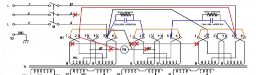
Now... in a THREE PHASE transformer, you have the A and C coil sides, with B in the middle. One could use three SINGLE_PHASE transformers, and just wire them in wye or delta, and be done with it, but since the phases are running in 120 degree intervals, rather than 180-degree opposites, it is possible to connect the three cores TOGETHER, and SHARE a certain amount of the magnetic alternation, so that the end result is a smaller, lighter core, and if designed well, even greater efficiency in terms of core loss.
The catch being... what happens between A and C, must also include some action in B.
It's like having a three cylinder engine, using common intake and exhaust. If you kill one cylinder, the tuning of the other two cylinders falls off... because the intake and exhaust pulses are no longer 'helping'.
In a single-phase transformer, the magnetic alternations go up and down. (read 'Right Hand Rule').
In a three-phase transformer, the magnetic alternations go up and down in each core, but must go between A->B, B->C, C->B, B->A.... in a figure eight. That means, when A is pushing south, the outflow goes down, then right, then up through B (so B is opposite A), and then out the top of B, into the top of C, then down... then left, then up B.
So what we're doing, is making this transformer CIRCULATE. Now, it naturally WANTS to, but when you just drive A and C (inverted), B has no real reason to want to play. It's like two girls swinging a pair of jumpropes and Charlie Brown stands there watching. If we push Charlie in (like, powering B directly from A or C), he'll get clocked in the head by one of the jumpropes.
In this conversion, the REASON it's happening, is because we're feeding B with capacitors, and as a result of the INDUCTANCE of B, and the Capacitance we've added, DELAYS pushing just long enough so that SNOOPY jumps in BETWEEN the rope swings, and then, all he has to do, is jump when they're both DOWN... and now, we're skipping Double-Dutch.
Ah, I digress...
Okay, so yeah, the thyristor board, having no 'brains' is a good thing. All it's doing is firing the SCR when it gets to a certain point in the rise... like a lamp dimmer.
Let's try next step- increase capacitance.... go up with both sides, work your way up with whatever you have (don't hafta be 'pretty' with it, just hook up and gun it), and see what happens. When you hit the 'sweet' spot, it'll wake up and burn metal. If you get to oh... 220uf or so, and don't see a change, then it's time to drop back and punt.
I suspect we just haven't found where this transformer wants to come out and play.