What's new
What's new

Current transformer selection?

Grigg

Hot Rolled
Joined
Jun 25, 2007
Location
Lexington, VA
Hello,

I'm trying to figure out what current transformer to shop for given the following use:

Adding a 3/4 HP 3 phase motor as alternate power source for a diesel powered ice cream machine, remove one belt install another, plug it in and churn.

The electric motor is 3.6 amps at 220V.

Using VFD as phase converter and voltage booster so this can plug into a normal 115V outlet.
TECO FM50-101-C AC Drive, 1 HP, 115V 1 PH Input, 230V 3 PH Output, 4.2FLA,
Input is about 16 amps max at 115V single phase.

The meter is an old one and shows fractions of full load. Load will increase as the ice cream sets up; so with some experience I'll know from the meter when a batch is almost done. Not necessary that the scale be calibrated so long as the needle movements are useful as above.
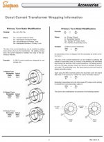
On the face of the meter "C.T. RATIO 100:5 and FS=5A" which I take as current transformer ratio and full scale amps.

I think it'd be best to measure/indicate current from the 115V input to the VFD and not the 3 phase output, I'm guessing 5-10 amps might be usual range and not more than 15-16 amps.

How do I calculate and decide which current transformer to shop for?
And/or will most any 100:5 current transformer work if I loop the load wire through as many times as needed to get a useful reading on the meter?

Pictures of components below. The VFD, input circuit breaker, meter, and current transformer will all be in a stainless box mounted on the motor.
I have already tested the motor on 3 phase with a double batch and it performed well, didn't lug down noticeably or heat, unfortunately I wasn't able to measure amp draw.

Thanks,
Grigg


IMG_2602[1].jpg

IMG_2745.jpg

IMG_2742.jpg

IMG_2743.jpg IMG_2744.jpg
 
Hello,

I'm trying to figure out what current transformer to shop for given the following use:

There is nothing "wrong" with your approach, it can work, and work well.

But.. your VFD already HAS the information you seek - current being monitored rather accurately and constantly - as a necessary part of just doing its basic job. Not exceeding the current limit set-points.

Seems to me, given that most VFD have options to get information they work with back out for remote monitoring over a network that can even span continents, not just local pumps, conveyor lines and such - that it would require less "inventing" and perhaps even less money, to just arrange to display the data already there - load current draw.

Might need a "network card" option. Or not. Might be on test terminals or connector.

DC Drives provide that output as standard, buffer it so no harm if shorted, and even specify what meter to use AS a "load meter" and how to calibrate it. All part of their "Day Job" already. External circuitry can then rely on that as predictable and accurate for more than just a meter. It can control "other stuff".

On a VFD, it might even be one of the available options for what one wants it to present on the display.

Not a new need. Common one, rather. Been built-in arredy for Donkey's Years. RTFM.

2CW
 
Agreed with procrastinator. I have a phase converting drive on my lathe, it will show current output on the display.

However, if it reads to one decimal place, it may not be precise enough to show the difference between ice cream that's done and not done.
 
Agreed with procrastinator. I have a phase converting drive on my lathe, it will show current output on the display.

However, if it reads to one decimal place, it may not be precise enough to show the difference between ice cream that's done and not done.

Love/hate/respect/nostalgia relationship with Diesels most of my life.

There are some bitchin' good governors out there. I don't expect that all that many of them were ever directly optimized for ice-cream making, though.

So there is - or needs to be- some "third party" assistance here.

If this were my challengs, I'd want a solution that worked for EITHER mechanical drive or electrical drive.

Something like a strain-gage as one player of a flexible mounting system.

Put that on one of a motorcar's engine mounts - as they do - and one can track torque. The tachometer to calculate HP is usually already there. Or is "don't care", as torque was really all one needed. These days? Probaby already being tracked inside the OBDC guts, and easily read-out.

"Farm boy" as I am? I'd just chuckle, do the flexible mounts, and run a wand of day-glow driveway marker up where the mixing drum's tilt of that wand let me put a "done" mark on a dial.

And or a cutoff-switch.

"KISS" method.

:)

3CW
 
Use a chart recorder. Now that I think about it, that would be a good project in the computer side. Run a hand built program of a chart recorder on a LCD screen which displays the red/black/green pen lines. Monitor motor voltage, current, and temperature.

For you I would use something like a Shoreline Hall Effect Sensor. The more expensive variety has a hinged plastic piece that allows you to install a wire without breaking a connection. I'm ok with the fixed hole style.

AC current up to 250A
Input: 10-15VDC
Output: 0-2.5v
Frequency: 0-400Hz
Accuracy: 1%
 
Thanks for the input,

Procrastinator, I understand exactly what you're proposing and having the VFD display amps would be a fine solution. Before buying the drive I read the manual and even called the vendor to see if running amps could be displayed by default. This being a simple and cheap drive the answer is NO. (unless we're missing something?)

Interesting thoughts too on a strain gauge, a mechanical one sounds like fun... but not what I'm after here. The diesel does change it's tune when the ice cream is getting stiff.

I know this ice cream maker project is already way more complicated than necessary (in almost every detail) and that there are countless other ways to "indicate load" and generally further complicate things..

I'd really like to use the neat old load (amp) gauge with a current transformer. I generally understand how that works but not enough to decide which current transformer to shop for.
What specs are important, and or is there some specification of transformer that makes this particular setup work easier/better than another? What's the math?

Thanks,
Grigg
 
Sure, This shouldn't be expensive and I intend to browse ebay for the needed parts.
I don't yet know what to look for?


With the explanation of the problem and specs for existing components is there a math problem that explains and answers what current transformer will sense the input amps and provide a useful indication on the meter?
 
Any 5A secondary CT should work fine with that meter. With 5A applied, the needle will be at full scale, or at the right-hand side of the red (6/4). If my math is correct, 3.33A should get the needle to the right-hand side of the green ("Rated") mark. If you use a 100:5 CT and loop the primary wire through 10 times, it works out to be 10:5. In that case, 5A flowing through the primary wire will move the needle to 50% of full scale.

You can pretty much use whatever ratio CT you want, with however many loops of wire through the primary you want. For a motor that small, I'd be inclined to use a smaller CT ratio.

I don't have any experience with that particular VFD. Some VFDs have an analog output you can program. If this VFD has that capability, you could program the output for motor current, and hook up an analog meter to that.

DO NOT put current through the CT primary if the secondary terminals are not shorted. A substantial voltage can develop across the open terminals.
 
Sure, This shouldn't be expensive and I intend to browse ebay for the needed parts.
I don't yet know what to look for?


With the explanation of the problem and specs for existing components is there a math problem that explains and answers what current transformer will sense the input amps and provide a useful indication on the meter?

AFAIK, it isn't any more complicated than the Ampere-turns maths at core.

Never had to give it a thought. The makers of meters and coils did it all ages ago and standardized their parts so the ranges came out easy to kit-up together from parts bins.

Same as shunts being made for use with meters of only a few ranges, tachogenerators in common Volts per 1,000 RPM classes, rubber tires for cars, trews, hose, hats, shoes, condoms, or tins of beans.

I don't care to "invent" any of those. Been done already.

I just use them. Not necessarily interchangeably.
 
In the powerhouse electrical world 5 amp meters are standard for this service. A 100:5 current transformer is common. My suggestion is to measure the current at the end point with a clamp on meter and pick your current transformer accordingly. You do need a current transformer instead of a regular voltage transforming one. Typical voltage transformers are run at a flux density around 15,000 Gauss while current transformers peak at about 3,500 Gauss to stay in a more linear region. The turns ratio is also buggered to make up for losses in the core. I am getting rid of my junk to reduce the load on my heirs, so I probably have a CT you can have for shipping.

A book about WWII submarine duty related the time a cook had trouble understanding just such a meter and let it keep running until it fried the motor. The ship electrician rewound the motor and carefully explained to the cook how to monitor the current and shut off at the right moment. The cook promptly burned it up again. Meanwhile, they were facing mutiny because ice cream was one of the few pleasures the crew had. After rewinding the motor again, the electricians removed the numbers from the meter and painted green and red arcs, like your meter has. No more trouble.

Bill
 
the electricians removed the numbers from the meter and painted green and red arcs, like your meter has. No more trouble.

Bill

Thanks for that.

Graduated Officer's School a long time ago, but it wasn't until now I understood why an "Officers' Model" wristwatch didn't have all those HANDS on it like the ones the Sergeant's wore.

:)
 
In the powerhouse electrical world 5 amp meters are standard for this service. A 100:5 current transformer is common. My suggestion is to measure the current at the end point with a clamp on meter and pick your current transformer accordingly. You do need a current transformer instead of a regular voltage transforming one. Typical voltage transformers are run at a flux density around 15,000 Gauss while current transformers peak at about 3,500 Gauss to stay in a more linear region. The turns ratio is also buggered to make up for losses in the core.

the flux in the core will be according to the resistance and inductance of the amp meter and the ct. But it would be difficult to find an appropriate voltage transformer in this case. For example, if you could find a voltage transformer with a 15 to 20v 5 amp secondary and a 6.3v 15 amp secondary, that would certainly get you a ~3:1 ratio which would be appropriate for connecting that meter to the input of the vfd.. but such a transformer will be very hard to find.

It appears to me that a 20:1 (100:5) transformer would take that 5 amps full scale and make it 100. 70 amps being rated load, perhaps it came off of a 16KW generator? Anyhow in my opinion the amp meter is usable as is for directly measuring the motor phase current. the color bars are in approximately the right place, but the no load amp draw of the motor and other issues will limit the usefulness of the meter as an actual load meter.

for the time and trouble of getting a current transformer of the right ratio (15:5 or 20:5) to work with that meter for the input side, you could probably find a 15 or 20 amp ac amp meter such as this one Weston Model 528 AC Amp Meter Working and Tested | eBay and install it on the input.

I don't know how moving iron ac amp meters handle the 50% power factor drawn by a voltage doubling single phase rectifier... so YMMV.

15:5
1 NOS Midwest Elect. Prod. Inc, CURRENT TRANSFORMER 2CT115B Ratio 15/5 | eBay
20:5
Instrument Service Current Transformer Ratio 2:5 3CT63 1"D | eBay

cheaper, but might take 3 weeks to get here:
2/5 Current Transformer For AMP Meter Gauge 91122334616 | eBay


Some of these current transformers require you to coil the wire through several times.

so in all honesty you will probably need a custom ratio to get the needle in the yellow when the icecream is done. so i recommend just buy a 100 or 200:5 coil and wrap the primary coil through the coil the number of times you need to get the ratio you want.
 
Shoreline and CR Magnetics. The green one is for DC but the one for AC is the same size. The Shoreline (red & black) with output of 0-2.5V indicates 0 - 250 A . Use a small DVM. Voltage * 100 = Amps. Other combinations are possible.
 

Attachments

  • DSC_0959.jpg
    DSC_0959.jpg
    58 KB · Views: 125
An iron vane meter will yield true rms values, a D'Arsonval/Weston type meter only gives true values for a pure sine wave.

Tom

An ignorant Thermistor bead mounted in a well-chosen location will probably provide the cheapest indication as to when the ice-cream has stiffened and is loading-up the motor.

It is a simple sensing task, major change-of-state, same family as hand power tool torque clutches to not snap fasteners, not a critical feedback control loop.
 
The flux density is calculated from the voltage developed at the meter terminals and the core cross section. Hook a Variac to a low voltage transformer and use it to drive the meter to full scale and measure the voltage. I haven't calculated one for a while so I will have to look up the formula to be sure. I used to do the calculation in my then much younger head. Actually, the meter would work as is in one leg of a three phase supply. Personally, I would find the capacitor that would produce a good third phase at the full load for a static converter and not bother with the VFD at all. Never mind all the nonsense about "balancing", hook it to a 120-0-120 line and read the voltage on the generated leg referenced to the common as if it was a high leg three phase line, 208 volts. When you get it right, put the ammeter in one of the 120 legs without a current transformer and it should be close enough.

I had to produce a replacement load meter for a 60 hp grinder motor. I was able to purchase a scale with colored arcs for a 4" Simpson ammeter but it read a little high. I just unwound turns on the ammeter coil until I got it right.

If you are determined to use a current transformer, I will send you a toroid core. It won't take that many turns and you can wind it by hand. Done it many times.

Bill
 
An iron vane meter will yield true rms values, a D'Arsonval/Weston type meter only gives true values for a pure sine wave.

Tom

The non linearity of his meter implies that it is a vane type. As I said in the previous post, the coil in those meters is a stationary spool surrounding the vanes. It is easy to change the coils and I have converted them to ranges the designer never dreamed of.

Bill
 
Hi Grigg, To use your cool old load meter, I would consider a 75:5 donut transformer and here's why.

You desire a 15A full scale reading and a special wrapping on the leads could yield a 13.75A full scale reading.

Starting with a 75A donut, each time you wrap the secondary (motor load wire) through the donut you reduce the current required for full scale reading by half. Two wraps of the load wire gives a full scale reading with 18.75A of current.

Then you can also wrap the donut with the primary lead (donut output wire) to affect the ratio. Can be additive or subtractive depending on the direction of winding. The primary (output wire) can add or subtract 5A per wrap.

An 18.75A full scale with two secondary wraps, then minus 5A with one primary wrap, yields a full scale reading of 13.75A right where you claim you need to be.

With a 100:1 donut you could get adjusted to 25, 20, or 15A full scale reading.

I would measure a finished batch of ice cream with the VFD and a clamp on, and try to aim the finish load point with the orange section (5/4), on your load scale.

Cut sheet PDF file for this modification found here.
Happy tinkering...:cheers:

SAF Ω

attachment.php
 

Attachments

  • DonutXformerAdjustment.jpg
    DonutXformerAdjustment.jpg
    74.6 KB · Views: 1,094


Back
Top