What's new
What's new

Cutler Hammer drum switch wiring for lathe

Kenzman

Plastic
Joined
Apr 15, 2010
Location
NS Can.
Hey , I've been doing some searching around for a diagram to wire up a C-H drum switch to a 220 single phase Leeson motor with no luck . The motor is standard NEMA wiring I believe so I would think it would have been easy to find a diagram but so far no luck . I did find some topics on the forum here but the images have been removed or it just won't let me see them . While we are at it I've been told by a couple of folks that I shouldn't even bother with reversing and maybe they are right , I just thought if the switch was in the machine why not use it . One of these folks is an older gentleman that rewinds motors , which is where I got the single phase motor and a manual starter switch . We were looking at the cover for the drum switch and it had HP ratings for all the different voltages and phases and the switch is marginal for the HP but he said if I just used it as an off and on switch I would have spare contacts for when/if they burnt up . So the other day he called me back and asked me to stop by , he was converting and 3 phase magnetic starter to single phase for me and recommended maybe just using the drum switch to activate the magnetic switch to prolong the life of the drum switch . Now I am not a machinsit or an electrician by any means , and I ended up having more options than I could shake a stick at . Any thoughts , input , diagrams would be greatly appreciated .

Sorry the post is so long-winded , just trying to give some background to my situation , and I'm sure he would make me up a diagram but he is in the neighbourhood of 80 years and I don't want to be a pain in his side .

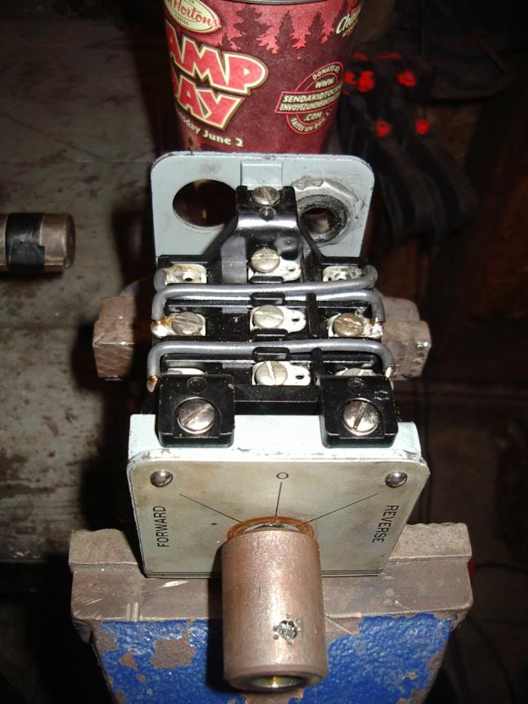
Here's the drum switch

drumswitch2.jpg


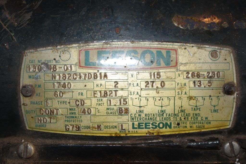
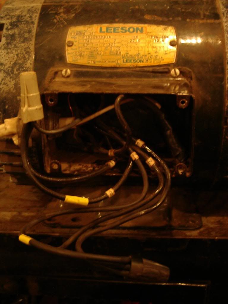
and here is the motor , the two wires with the yellow tape are 5 and 8

motor2.jpg
 
It looks like the drum switch is currently jumpered so you would be switching the same circuit on and off no matter which direction you turn it to. In order to use it as a two circuit switch you need to remove the wire jumpers. The drum switch is just a 3-pole double throw switch. If you are running the motor straight off the drum switch with no starter the power is brought into the switch and connected to the terminals that run down the center of the switch like this:

DRUMSWITCH.jpg


You would connect the forward winding of your motor to which ever circuit side has continuity with the center poles when you set the switch to "forward". The reverse winding connects to the other side. If you are using a starter then it has to be the reversing type with two mechanically interlocked contactors and you use the drum switch to control your power to your starters coils in a similar way but that is a little more complicated and you may want to bring in some help to wire that.
 
Ron's advice is correct, for a *three*phase* motor. Because you want to
do this leeson motor which is single phase, and you want 240 volt connections,
it won't work if you follow it.

Take a better photo of the nameplate on the motor I would suggest.

The drum switch will work fine all by itself for this motor.
 
I guess I'm screwing something up, that's why I hate answering these things. All I'm really trying to do is point out how the drum switch itself works, not trying to give you wiring advise. The connections within the motor depend on what you have for a motor. There is no way to tell by your picture. Here is a link to some common motor connections but Jim is absolutley correct in suggesting you get the model number off of your motor's nameplate so you can get the correct connection diagram from Leeson.

Motor Connection Diagrams

After looking at the diagrams I would say don't change anything with those jumpers yet. They look like they were added so the switch could be used for a single phase motor. Get your diagram before doing anything.
 
Last edited:
Yea , I was thinking the one leg that heads strait into the motor would go onto the one that is jumpered straight across and then 5 and 8 would go onto the criss crossed ones , but when I try to figure it out my thoughts get criss crossed :crazy:

Here's a picture of the name plate...

BeachPlayingandGrad265.jpg
 
The motor can be wired 120 or 240 volt.

Just to be sure, it sounded like you want to use 240 volt connections
for this, according to your original post.

Is that right?
 
Hmm. The 120 volt version for this is dead simple, the 240 one is a bit more
complicated as one wants to, in principle, interrupt *both* incoming hot leads.

Do you feel comfortable poking around in the innards of the motor?

The point here is that reversing leads 5 and 8 as the diagram shows,
basically requires two poles on the drum switch - the two poles that
are cross wired, which in the photos show, are the lowermost two poles.

This leaves only one pole for interrupting the incoming power, which is
fine for 120 volt service, but not really the best for 240 volt as doing that
means the motor will stop, but all the internal wiring on the motor will
still be up at voltage from the other hot leg.

Not desireable.

In most dual voltage motors there are two run windings, and one start winding.
For low voltage the two run windings are put in parallel, connected across the
line. The start circuit (centrifugal switch, start winding, and start capacitor)
are likewise put across the line. So the guess here is that one run winding
has ends at T1 and T2, the other run winding is T3 and T4. T5 and T8 probably
the start circuit. So the diagram shows 1 and 2 across the line, 3 and 4 across
the line, and 5 and 8 also across the line.

For high voltage connection (240 volt) the two run windings are put in
series and one end of the starting circuit is put to the centertap between
the two - effectively feeding it 120 volts. The guess according to the
diagram, T1 is one end of one run winding, and the other end of that
winding is T2 which is put directly to T3 and the other end of that is T4 which
goes to the line. So the two would be in series that way. The centertap
between the two windings then is the common connection T2 - T3 which is
shown on the diagram. Which is where they have T8 also tied, T8 being one
end of the start circuit.

The guess would be that the motor would reverse fine if, instead of interchanging
5 and 8, an alternative method were used: Leave T8 hooked to the centertap,
and put the other end of the start circuit (T5) to either T4, or to T1. That way
the start circuit phase is reversed.

Now all this is pretty complex and means you have to open up the motor and
dink around inside to verify the connections so you don't smoke something.
But the overall goal would be (and here the numbering is WRONG on my diagram
because it was for a different motor) to get a circuit that looks like this:

wire.jpg


this allows reversing for the 240 volt connections, AND interrupts both incoming
hot lines. I spent an extra wire to use the overtemp switch in the motor.

If you can find a nearby sparky to sort though this, maybe he could help, or
if you change your mind and go with 120 volt service, it would be simpler.
Possible somebody like Peter H. knows how to use a 3 pole, two position center
off drum switch to reverse a 240 volt motor, maybe some trick he knows.

Jim
 
This will reverse it, BUT you will need a separate switch (or cord and plug) to be the "disconnect", because it does not break both sides of the line......

That need not be a safety issue, since the drum switch is to "operate" the machine, and should not be relied on to 'disconnect" it anyway.

You normally DO get access to both ends of the start winding IF the motor is dual voltage, as the Leeson in the picture is. T5 and T8 should be the start winding, as they get reversed to reverse rotation

If you really want total disconnection in center, use the single contact to run a contactor or relay to connect to the mains..... naturally to do that you wire straight thru instead of having the switch where I show it in the one "line" or "mains" wire.

drumswhivolt.jpg
 
I just checked the motor , T2,T3,T5 are twisted - T1,T8,L1 are twisted and T4,L2 are twisted . Different from the nameplate but it did seem to work OK , although we didn't revrse the direction . I do have a manual starter switch but it is 3 phase with 23 amp "heaters" . So would that be roughly 7.5 amps per heater on 3 phase ? Would it work as 15 amp on single phase or does it need all three legs to trip and give the intended protection ?? Anyways that's kind of getting off on a tangent , if I can figure out which wires goes to which terminals on the drum switch I'd be happy for now . I'm not very good at making/modifying pictures on here so for simplicity I'll just call the terminals on the drum switch

1______4_______7, -------1 and 8 being jumpered

2______5_______8, -------2 and 7 being jumpered

3______6_______9, -------3 and 9 being jumpered

and 4,5,6 being center "OFF" position

I had thought originally that I would take L2 to no.6 , and T4 to no.3 ,no.9
Then take T5 and T8 to the criss crossed ones but that is when I started getting confused , seems like it should be so simple . Maybe it is and I'm just being a little too appehensive but I hate tasting electricity and I certainly don't want to smell it coming out of the motor I just paid for . If it does get wired up with one side being energized even when turned off , will that cause any ill effects to the motor if 1 leg is energized too long without spinning the motor ?

Here is a picture of the manual switch I got incase someone may have an opinion on it .

starterswitch.jpg
 
With one wire still connected, nothing happens...... no ill effects from that if the insulation is good.

You can add a disconnect, use the plug, or control a relay with the single contact, without affecting the reversing and on-off functions. I generally like to disconnect all hot leads, and that is required of a "disconnect"...... but breaking teh circuit is "functional", just as the internal motor thermal overload does.

Your overload switch unit looks to be adjustable, not heater-based, but is not calibrated on the dial. You may be able to look up what the range is, it may well cover your application.

it looks to be set full up now, if that is 23 A, it probably will go down to maybe 6 or 7 amps, and would then cover your 13+ amp rating. You might have to set it..... either with a test, or by setting it low, and adjusting up if it nuisance trips
 
Hmm. The 120 volt version for this is dead simple, the 240 one is a bit more
complicated as one wants to, in principle, interrupt *both* incoming hot leads.

Do you feel comfortable poking around in the innards of the motor?

The point here is that reversing leads 5 and 8 as the diagram shows,
basically requires two poles on the drum switch - the two poles that
are cross wired, which in the photos show, are the lowermost two poles.

This leaves only one pole for interrupting the incoming power, which is
fine for 120 volt service, but not really the best for 240 volt as doing that
means the motor will stop, but all the internal wiring on the motor will
still be up at voltage from the other hot leg.

Not desireable.

In most dual voltage motors there are two run windings, and one start winding.
For low voltage the two run windings are put in parallel, connected across the
line. The start circuit (centrifugal switch, start winding, and start capacitor)
are likewise put across the line. So the guess here is that one run winding
has ends at T1 and T2, the other run winding is T3 and T4. T5 and T8 probably
the start circuit. So the diagram shows 1 and 2 across the line, 3 and 4 across
the line, and 5 and 8 also across the line.

For high voltage connection (240 volt) the two run windings are put in
series and one end of the starting circuit is put to the centertap between
the two - effectively feeding it 120 volts. The guess according to the
diagram, T1 is one end of one run winding, and the other end of that
winding is T2 which is put directly to T3 and the other end of that is T4 which
goes to the line. So the two would be in series that way. The centertap
between the two windings then is the common connection T2 - T3 which is
shown on the diagram. Which is where they have T8 also tied, T8 being one
end of the start circuit.

The guess would be that the motor would reverse fine if, instead of interchanging
5 and 8, an alternative method were used: Leave T8 hooked to the centertap,
and put the other end of the start circuit (T5) to either T4, or to T1. That way
the start circuit phase is reversed.

Now all this is pretty complex and means you have to open up the motor and
dink around inside to verify the connections so you don't smoke something.
But the overall goal would be (and here the numbering is WRONG on my diagram
because it was for a different motor) to get a circuit that looks like this:

wire.jpg


this allows reversing for the 240 volt connections, AND interrupts both incoming
hot lines. I spent an extra wire to use the overtemp switch in the motor.

If you can find a nearby sparky to sort though this, maybe he could help, or
if you change your mind and go with 120 volt service, it would be simpler.
Possible somebody like Peter H. knows how to use a 3 pole, two position center
off drum switch to reverse a 240 volt motor, maybe some trick he knows.

Jim


Hey Jim:

Your excellent explanations are timeless.

7 years after your post, I am also considering rewiring my motor from 240 to 120 VAC because my boat has a European Electrical System which is 380 volt 3 phase with the voltage between the neutral and any phase is 220 volts. The neutral leg is essentially ground, so in my case (due to the motor construction, I think) using 240 volt input puts the motor and lathe frames at 115 VAC.

I disconnected the ground wire from the motor to the case of the C-H Drum Switch and also disconnected the metal rod from the motor stand to the lathe frame, and that removed the 115 VAC from the lathe frame and keeps the 115 volts at the motor only.

Of course when I attach the rod, with tape for insulation, the fit was so tight that the tape opened up and made an electrical connection putting 115 VAC back on the lathe frame.

On the boat, I use an isolation transformer to disconnect the boat from the shore grounding system and also create 120 volts on the boat. Even here, I can only use one leg to power my equipment because wiring it normally puts the tool frames at 115 VAC.

Since I have a 1 HP motor on the lathe, it draws 12.5 Amps at 120 VAC, and I would rather not add that load to the existing load as it would increase the unbalanced load on the two legs of the transformer.

So my preferred path is to keep the feed for the lathe at 220 VAC from the main electrical panel on the boat and isolate the mid-level (115 VAC) grounding in the 1 HP motor from the frame of the lathe.

But, if I had to change to 120 VAC, I was worried about the C-H Drum switch not working properly, but thanks to your detailed explanation, I now know that the only wiring changes will be made at the motor putting the two run windings in parallel.
 
Problem Solved: Reversed the two input lines so that the neutral line is the one being passed through and the 220 VAC line is the one that is switched on and off as well as the one that is feeding the correct side of the windings.


Back
Top