What's new
What's new

Des-co 20HP phase converter voltage at 260v.

Neo6

Aluminum
Joined
Mar 9, 2014
Location
Nevada
Hi folks,
I just bought a Used Des-co 20HP, when I start it I can read 260v across all legs with a variance of about 2v, the phase converter does not have anything connected to it when I test it is just the motor putting power out, is the phase converter at 260v because is not under load? The CNC machine (Fadal 3016) I am going to power up requires 230 VAC according to the manual. Can I safely use this phase converter? Thank you!
 
I understand about your 260VAC +/- 2VAC across all lines.

What instrument are you using to measure VAC.
With no Des-co, what is your incoming single phase voltage reading? Is it 260VAC?
What does the idler motor nameplate say?
 
What Ron said......

If ALL the lines read 250V, then the converter seems like it is doing what it should, reproducing the incoming voltage at the 3 phase output. Ought to do that at 230V, if you feed it 230V.

The 260V is about 13% high for 230V, and CNC seem to be notorious for demanding closely controlled voltage. Probably too high, although we do not know what it may fall to under load, especially the "generated leg". Most RPC will let the "generated leg" drop under load.

You could "buck down" the input to the RPC, or possibly the 3 phase output. That should let you get to something closer to what the CNC wants.

MOST electrical equipment is supposed to tolerate a variation of +- 10%, per UL. For 230V that would be up to 253V max, for 240V up to 264V max. CNC equipment may specify closer limits.
 
Thank you gentleman I appreciate the help, I am not at the location where the Phase converter is at, I will check and report.
I used a voltmeter to check the voltage across the legs. I know the input has to be 240v since the machine was connected in a residential area however I have not checked it yet but I will and reply. Once more thank you!
 
I understand about your 260VAC +/- 2VAC across all lines.

What instrument are you using to measure VAC.
With no Des-co, what is your incoming single phase voltage reading? Is it 260VAC?
What does the idler motor nameplate say?

Hi,
I am using a multimeter to measure VAC, the single phase is at 240v, the nameplate is kinda of a pickle I see a sticker that has a logo for "Overnite" with a "SHR 385 537 283" I google it but nothing is coming back as details for an electric motor.
The motor was against the wall and could not see the other side of it, is so heavy that I need someone to help me move it, I'll get some help to check it tomorrow and post if I found any more information. Thank you.
 
What Ron said......

If ALL the lines read 250V, then the converter seems like it is doing what it should, reproducing the incoming voltage at the 3 phase output. Ought to do that at 230V, if you feed it 230V.

The 260V is about 13% high for 230V, and CNC seem to be notorious for demanding closely controlled voltage. Probably too high, although we do not know what it may fall to under load, especially the "generated leg". Most RPC will let the "generated leg" drop under load.

You could "buck down" the input to the RPC, or possibly the 3 phase output. That should let you get to something closer to what the CNC wants.

MOST electrical equipment is supposed to tolerate a variation of +- 10%, per UL. For 230V that would be up to 253V max, for 240V up to 264V max. CNC equipment may specify closer limits.


Hi gentleman,
I fully tested the phase convertor today, I am getting 244v into the convertor, when I measure the output I am getting 244v across legs "A" and "B" however when I measure across leg "C" I get 260v.*
I am guessing the generated leg is "C" hence it is putting out 260v, is this normal? would it stabilize to 244v like the other 2 legs once it is under load?
I can't find a specs plate or brand in the motor, I open the cable compartment still nothing, all I can say is that the motor is blue, large and got to weight about 100-150lbs, I have to lift it with my engine hoist to move it.
The "Overnight" tag on the motor that I mention in my other post for what I can see in Google I think it is an old shipping company that UPS acquired so I think this label was put in when the motor was shipped and never removed.
Anyhow I hope you folks can help me understand if this phase convertor is safe to use in my CNC. Thank you.
 
A generated leg voltage can be high like that. Then the voltage drops when under load. In my experience it is like that when run capacitors are in place. The idler will vibrate a little more than usual when not under load. When loaded the voltage should drop but you won't know for sure until you try it. A few seconds under power will tell you. Then you can determine what the balance between phases looks like. Any capacitor alterations can be made to get better readings. I think most people work it like that.
 
A generated leg voltage can be high like that. Then the voltage drops when under load. In my experience it is like that when run capacitors are in place. The idler will vibrate a little more than usual when not under load. When loaded the voltage should drop but you won't know for sure until you try it. A few seconds under power will tell you. Then you can determine what the balance between phases looks like. Any capacitor alterations can be made to get better readings. I think most people work it like that.

Thank you Ron! I appreciate the help, I feel more confident now. I won't know for sure until I test it under load as you mention, with that said to test should I connect the CNC machine and turn it on just idle and test the generated leg to see how much voltage I am getting? I see you mention for a "few seconds" I assume that is fair warning that I should be at the ready to turn it off if I still see 260v before I damage something.
Could you point me to more information on how to make capacitor alterations to get better readings? I might try that :) Thank you again for your help.
 
The 260V is within the "normal" for a 240V line maximum voltage. As mentioned, equipment that carries a UL recognition or listing has to tolerate up to 264VAC on a 240V line without "creating a dangerous condition". That means in practice that it should tolerate that voltage without damage. That said, you'd need to refer to the CNC manual to find put what the actual specified maximum it can tolerate is. I am leery of the "plug it in and try it" approach, I like to make sure that the device SHOULD work on the supplied voltage frequency, etc before I feel justified in "plugging in and trying it". So I would check the manual, and be ruled by what it says.
 
The 260V is within the "normal" for a 240V line maximum voltage. As mentioned, equipment that carries a UL recognition or listing has to tolerate up to 264VAC on a 240V line without "creating a dangerous condition". That means in practice that it should tolerate that voltage without damage. That said, you'd need to refer to the CNC manual to find put what the actual specified maximum it can tolerate is. I am leery of the "plug it in and try it" approach, I like to make sure that the device SHOULD work on the supplied voltage frequency, etc before I feel justified in "plugging in and trying it". So I would check the manual, and be ruled by what it says.

Thank you JST :) I did find this document for Fadal CNC machines ...

https://www.fadalcnc.com/media/pdf/Properly_Tapping_Fadal_Tranformers.pdf

there is a table that shows how to set the voltage for the CNC machine, the document says to pick the next higher voltage on a table of settings available for the machine, I am at 244v from the street, the next step up in the table is 250v although I see a 260v after that perhaps I should set it for 250v, I am hoping that once it is under load it will drop the voltage to the generated leg to match the other ones, does that sound correct? Thank you again I appreciate your help and Ron's I be lost without you guys.
 
Could you point me to more information on how to make capacitor alterations to get better readings? I might try that :) Thank you again for your help.

You have an expensive machine, so why take a risk. Can you look inside the RPC box and draw a circuit diagram of the components. Then take a picture of the diagram and post it here. That is what I would do.
 
With no further information, I would prefer to adjust the RPC output to better balance the voltages. If you had a consistent 260/260/260, I would say connect for 260. But you do not, and we know the 260V will drop under load. So it makes far more sense to adjust the RPC output so it is not as high, and then pick a suitable connection.
 
Sorry guys I just saw your replies now, I will take some pictures of the phase convertor and will try to make sense of the parts as much as I can, I am new at this hence I do not have too much confidence that I can recognize all the parts, I'll try and will post it. Thank you for all your help.
 
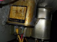
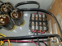
Here are a few pictures of the phase convertor, I would love to be able to make you guys a diagram of all the parts and how are they connected however I can't see labels and I know little about this stuff, I see a bunch of capacitors however only one label was visible, a white box that I do not know what it is along with that square qube where it seems to have jumpers.
Anyhow I am unsure if you fellas can make anything of this thing, yet again thank you!
 

Attachments

  • 20180624_212953.jpg
    20180624_212953.jpg
    94.7 KB · Views: 300
  • 20180624_213133.jpg
    20180624_213133.jpg
    91.5 KB · Views: 134
  • 20180624_213057.jpg
    20180624_213057.jpg
    92.4 KB · Views: 583
  • 20180624_213019.jpg
    20180624_213019.jpg
    94.6 KB · Views: 168
First picture:

The white box is a timer with adjustment control.
The square cube is acting as a relay to switch your start capacitor bank.
The black capacitors are your bank of start capacitors.
The metal can capacitors are run capacitors.

Second picture:

Capacitor is 50uf at 370Vac

The hot melt glue business should be removed and everything held with real clamps.
 
Thank you for the breakdown :) I was wondering about the hot glue \ silicon, I will remove all the glued items and re-mount them.
I was looking at other setups online, I really like that some of them have a start\stop buttons. Do you think that I could reuse this current parts and rebuild it to something better? Perhaps something with a start/stop button?
After taking a peek at the inside of the RPC do you have any tips in what should I check that could be generating the higher voltage in one leg?
 
There is plenty of posts that deal with your issue for remaking a RPC better. A start/stop button arrangement will require that you install a motor starter (a multi-pole relay).

I would disconnect a run cap and that should lower the high voltage in your generating leg. Draw out your RPC design and then compare what you have to other ones on the site.

You are awesome :) I'll do that. It looks like I have some homework to do, thank you for all your wisdom Ron!
 
One more question, there a diode in one of the run capacitors, you can see it in the second picture "Capacitor is 50uf at 370Vac" Should that be there, is that to terminate the series of caps? Thanks.
 
One more question, there a diode in one of the run capacitors, you can see it in the second picture "Capacitor is 50uf at 370Vac" Should that be there, is that to terminate the series of caps? Thanks.

I see a resistor, used as a safety device for discharging the capacitors Cannot quite see the value, but given that it appears to be a 1/2W part, it is probably a high resistance that will take a long time to discharge if the capacitors are not connected to the idler. The yellow band would indicate something in the hundreds of k-ohms.


Back
Top