Palak
Aluminum
- Joined
- Jul 12, 2013
- Location
- Pacific NW
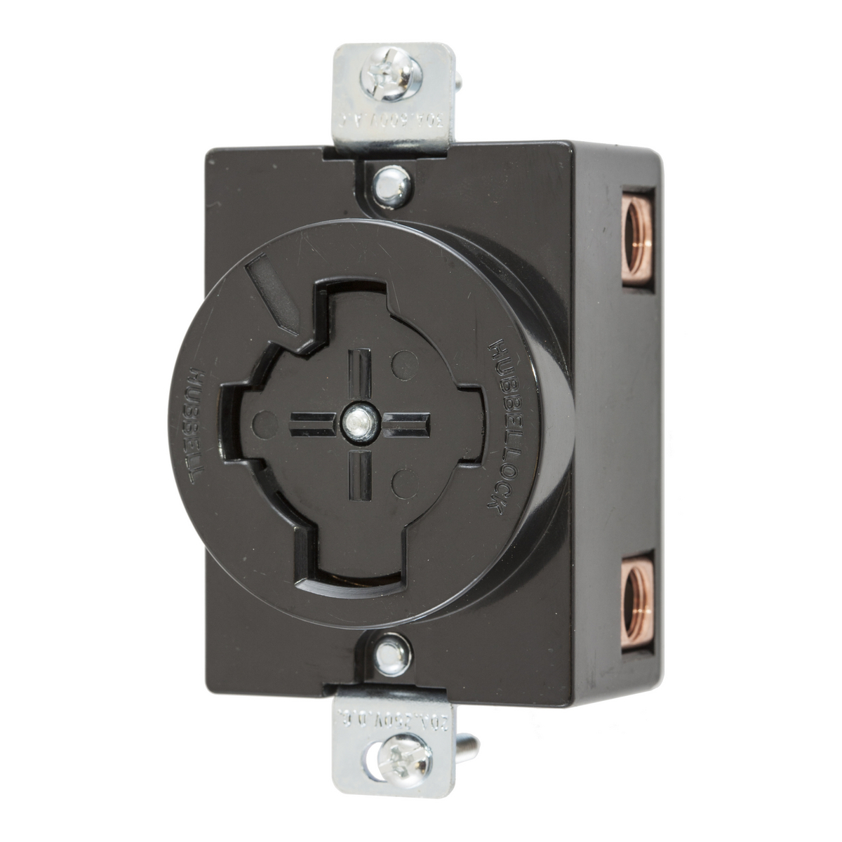
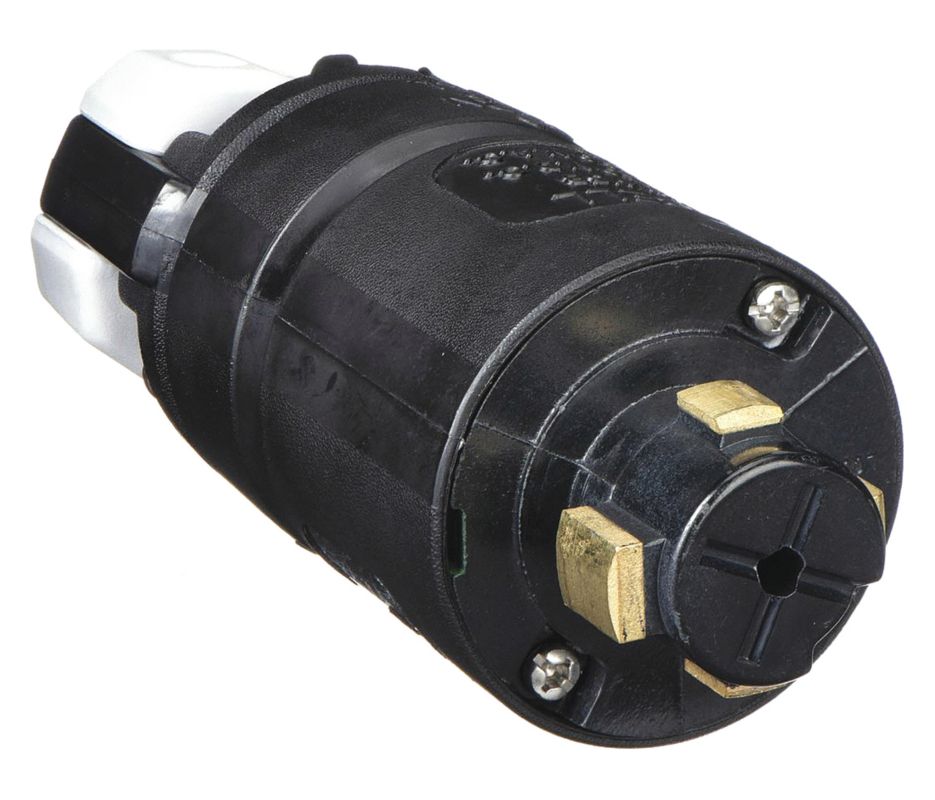
We have an older grinder with an integrated Hubbellock outlet built into it. The grinder runs off of 480V 3 phase, but it has a few outlets on it, including one that has a conventional 120V outlet. The Hubbellock outlets, at least from a few we have in the shop, appear to be able to handle from 240V through 600V.
What is the best and safest way to test the voltage of this outlet? The Hubbellock outlets don't seem to have a way to insert multimeter probes into them. We did plug an older 220V 3-phase pump into this outlet (naively assumed it was 220V), and the pump did run, but the casing got very hot after 5 mins and we shut it down (leading us to believe it might be wired at 440V).
Would appreciate any sage experience anyone could lend.