What's new
What's new

Dual float pump control

R8f1k

Aluminum
Joined
Feb 10, 2014
Location
Illinois
Anyone know how to wire a simple dual float switch? The configuration is four wires, two per switch, the switches can be NO or NC in the down position, they can be flipped to change NO or NC position. The goal is to have the pump turn on at the high point and shut off at the low point, but not to pump the tank dry. It would be better to keep some liquid in the tank to prevent a dry condition on a pump start up. The pump is currently hooked up to a 220V contactor, that starts and stops with closing the contacts. How do you wire something like this with 4 wires and 2 floats?
Below is the switch:
Float switch.jpg
 
High Level Upper switch NO and closes with high level
Lower Level Lower switch NC with high level NO with low level

Coli power goes to lower level switch which is serially connected to the upper level switch which is connected the contactor coil A1. Lower level switch out is also connected to spare set of NO terminals on the contactor back to A1 to form a latching circuit. A2 connects to other-side of 220V. It is also possible to put a timer circuit to prevent the pump from running too long should the lower switch fail to open with a low level. Would also use a thermal overload relay for the pump should it get clogged or freeze up.
 

Attachments

  • Hi Lo Level Contactor Control.jpg
    Hi Lo Level Contactor Control.jpg
    26.3 KB · Views: 32
You need to use an auxiliary contact on the contactor to form a sealing circuit. More or less the usual three wire start-stop arrangement save for the use of float switch contacts instead of pushbuttons.

stopstartmotor.gif
 
Both are excellent ways to execute the plan. I will post a photo of the contactor that I have, that will eliminate any doubt in which contacts I need to use. I'm pretty sure I know which to use, but I want to be sure.
 
They're the same way, just drawn differently.

You can also get a submersible float switch like this and have a foot or so of cable between where it is secured and the actual switch. When it floats up, it turns the contactor on, and when it falls back down, it turns the contactor off. You can have quite a large control range.
 
I can’t figure out how to add a photo with my phone, so I will just say that I have an NHD contactor, model C-90D
 
Here is a shot of the contractor. I can't figure out where to put wires for the floats. Any help is appreciated!contactor.jpg
 
13 and 14 comprise your N.O. auxiliary contact. 'Ma' in the diagram above. High limit N.O. contact goes in parallel with it. Low limit N.C. goes in series with both, preferably on the line side of them. It is best practice to locate N.C. control elements before N.O. control elements where practical. Simplifies troubleshooting.

Careful of that jumper between 5 and 13. Looks like you've got some existing control wiring that will have to go. Improperly sized & fused I might add. Add a 3A fuse for the control circuit. Two if tapped line to line instead of line to neutral.
 
Correct, the small wire (#20) are hard lined in the float switch, they are too small. I have a waterproof box that the switch will connect to and inside of that, there was going to be a fuse.

For clarity: 1) should I remove the jumper between 5 and 13? 2) I have 2 colors of wire, 2 red for the top float, 2 black for the bottom. Which color goes to which terminal on the contactor? I’m figuring one red wire on terminal 13 and the other on A2. Is this correct? And then where do the black wires go?
 
13 and 14 comprise your N.O. auxiliary contact. 'Ma' in the diagram above. High limit N.O. contact goes in parallel with it. Low limit N.C. goes in series with both, preferably on the line side of them. It is best practice to locate N.C. control elements before N.O. control elements where practical. Simplifies troubleshooting.

Careful of that jumper between 5 and 13. Looks like you've got some existing control wiring that will have to go. Improperly sized & fused I might add. Add a 3A fuse for the control circuit. Two if tapped line to line instead of line to neutral.

Got its sorted! Had to step away for a day and look at it again. Thanks guys!
 
13 and 14 comprise your N.O. auxiliary contact. 'Ma' in the diagram above. High limit N.O. contact goes in parallel with it. Low limit N.C. goes in series with both, preferably on the line side of them. It is best practice to locate N.C. control elements before N.O. control elements where practical. Simplifies troubleshooting.

Careful of that jumper between 5 and 13. Looks like you've got some existing control wiring that will have to go. Improperly sized & fused I might add. Add a 3A fuse for the control circuit. Two if tapped line to line instead of line to neutral.

Now, I have another issue with this arrangement. According to the manufacturer it says "Please Note : Float switch can not directly control solenoid valve or high power relay, AC contactor, etc. Small relays are required to transition." What kind of 'small relays' are they referring to?
 
Probably 12-24V AC/DC. Do they have a rated current/voltage?

You'd be looking for a small socketed DIN-rail mount relay.

Never used/installed/played with a DIN-rail system, any recommendations are appreciated.

These are the specs on the float:
Max Switching Voltage : DC110V; Max Switching Power : 10W;
 
Use a 24VDC DPDT relay use one side NO for the latch which is run off of 24VDC inclusive of the coil. The other pole NO to switch one side of the 240VAC going to the contactor or if you want you can get a 3 pole and switch both sides of the 240VAC to A1 and A2. Probably not the best thing to have 240VAC running to float switches in liquid. It is usually recommended to use a spike protection diode on the relay coil due to the reverse voltage spike generated when the coil opens. They sell a small plug in diode if you do not have any diodes laying around.

782-2C-SKT DIN Rail Socket DIN socket for 2P relay
https://www.automationdirect.com/ad...kets_-a-_accessories/relay_sockets/782-2c-skt
782-2C-24D ice cube control relay, socket mount, encapsulated push-to-test, 24 VDC coil voltage, DPDT, 15A contact rating, 8-pin, LED indicator(s)
https://www.automationdirect.com/ad...81_-z-_782_-z-_783_-z-_784_series)/782-2c-24d
Spike protection diode module, package of 5. For use with 782 series relays.
https://www.automationdirect.com/ad...-a-_accessories/relay_accessories/ad-bsmd-250

Power supply 24VDC (0.42A) to run the relay (these usually take around 0.07A)
RHINO PSL series switching power supply, 24 VDC output, 0.42A, 10W, 120/240 VAC or 125-375 VDC nominal input, 1-phase, enclosed, plastic housing, 35mm DIN rail mount, screw terminals, NEC Class 2.
https://www.automationdirect.com/ad...din_rail)/psl_series_(low_profile)/psl-24-010
DIN rail, slotted, 35mm, 7mm height, 4.9in length, plated steel. Package of 2
https://www.automationdirect.com/ad...sure_parts_-a-_accessories/din_rails/din6-p10


Ok, I'm new to this part of electronics.....I'm pretty good with late 1970's - 90's circuit boards...I'm good with most AC applications, single and 3 phase. This component....new to me. So, I APPRECIATE ALL OF THE INFO you have provided, but I don't want to screw up the next part. Will the system you recommend be able to work with a 3 wire NO/NC control? I will order anything you recommend to order, I just the quantity of each. I will also need a diagram of how to wire this up once the parts arrive. Can you help with both?
 
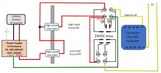
Example of low voltage relay for switching high voltage AC to contactor coil. If the AC coil is 240 VAC single phase you can pull the power after the breaker or fuse that feeds the power supply. Power supply even though is minimal power, typically they specify a 15A breaker. Make sure the contactor coil windings are 240VAC.
Example of a DIN rail mount breaker would be https://www.automationdirect.com/ad...rs_(gmcbu_series)/2-pole_(1a-63a)/gmcbu-2c-15
Level control with low voltage relay.jpg
 
Ok, bought 24VDC relays. They are 8 pin ice cube relays, 3 different brands, but all 24VDC-120/240VAC. I also have a variable input transformer: 100,120,210,240VAC/24VDC. Looking at your diagram, I'm lost on the square above the 24V relay. What are numbers 9,12,A1,A2? Is that another 24V relay? Here is a photo of the components I have. IMG_5177.jpg


Back
Top