What's new
What's new

M05 from high RPM kicking out my PT380

Rick Finsta

Stainless
Joined
Sep 27, 2017
I got my machine back up and running with a buck/boost taking it from 242V to 209-211V on the input side of the PT380.

Now, when the spindle decelerates, it will sometimes kick the Phase Perfect into some kind of error mode and turns off the machine control (it appears to be kicking out a leg of the 3-phase). The spindle then coasts to a stop. If I reset the breakers everything fires up no problem.

WTF?
 
Depending on where, and how the phase perfect measures its output current, you may be able to solve the problem by adding an additional line reactor (3% should do it) to the output of the phase perfect, followed by delta connected capacitors. (on the order of 60uF (or multiple smaller caps)) after the line reactor.

Your buck boost transformers after the capacitors also have a little bit of leakage inductance so you've formed an LCL filter between the phase perfect and the machine.

The reason why this may work is because the regenerative inverter front end of the spindle vfd may not have much of a filter on it, and while the rms current flowing back up the line should be within the PP's capacity, the peak value of the current is high enough to trip it.


There is a possibility the regenerative front end of the VFD has no inductor in its front end, and it relies on the inductance of the input 3 phase line to function properly without exploding. In this case you need to place the additional capacitors at the phase perfect (may not even be needed), and move the line reactor directly to the input terminals of the VFD.

I would be interested to know if they have have no filter.. you should see 3 inductors near the input circuitry of the vfd. Its hard to estimate how big they would need to be, but for a low frequency regenerative drive you would need something the size of a typical 3% line reactor for the capacity.. so 10 pounds of copper and iron for a 5 to 10 hp drive. For a high frequency design you would be looking for 3 inductors each the size of a golf ball in volume per 2-4 KW of the vfd's capacity.

I picked up some vfds from 5 ton hvac systems (24 amps at 240volts single phase) and the inductor they use for the power factor correction front end is about 3 inches by 3 inches by 2 inches in volume. that's about the size of the inductors you would be looking for in a similarly sized vfd with active regeneration, except there will be 3 of them.
 
You're a little over my head on a lot of that, but to be clear I am using a single buck/boost on the input of the PP no two of them on the output side.

I am also not following as to if you are saying the spindle amp in the machine cabinet will have a VFD inside of it, and I need to be looking upstream of that inside the spindle amp? I have no idea how the spindle servo on a machine center works LOL.

I can always just go back to feeding the machine 242V and see if that works by bypassing the transformer (why didn't I wire it with a bypass switch? I've screwed with it enough now that I should have).
 
the spindle with its regenerative drive is a VFD if its a 3 phase motor.

If you've got a dc motor spindle then the proper terminology is to call it a dc motor controller. or a 4 quadrant dc drive, etc.

either way it pumps current back into the line to slow down the spindle, to the tune of a lot of amps.


you could try running your PP at 240 volts then install two buck boost transformers after the PP in open delta configuration to reduce the voltage. Since the PP is current limited this will increase your capacity by ~10%. Combined with the leakage inductance of the buck boost tranformers it may solve your problem.


the PP is rated for something like 6 times its nominal "rating" for something like 15 seconds for the purpose of direct online starting of 3 phase motors. i have a hard time believing your spindle can dump enough current upstream to shut off the PP unless its got.. no filter (say 100 amp spikes of current but on average not nearly that much actual current) . in which case adding a line reactor may solve the problem.

It may be that the PP doesn't have symmetrical ratings, it may not be capable of dumping 6 times its rated load, upstream.

what machine are you running and which PP do you have?


the PT-380 is supposedly rated for 400 amps for 4 seconds. Its hard for me to believe it can upload 400 amps into the grid for 4 seconds but maybe it can.

in any case, you may be able to solve your problems by simply adding a 3% line/load reactor to the spindle drive directly, or to the entire machine.
 
It is a PT-380 but the wiring and breakers are only meant to support 15kVA. Machine is a Sharp SV-2412 so like 7.5hp (realistically) spindle.

There is a FANUC line reactor on the power to the drives in the cabinet already (at least FANUC calls it a reactor).
 
There is a reasonable chance that the problem is not with the PP at all.

If your power line is not "low impedance", meaning that the transformer feeding it is not very large, then feeding back a lot of energy can drive the mains voltage up too high on your side of the transformer, and the PP may be set to trip off if that occurs. According to the "tariffs" (powerco rules) that is generally required for anything putting "regen" power out to the line, but it may also be a protective feature of the PP, perhaps..

Your panel rating may or may not reflect the actual supply capability. Due to "diversity" of loads, it is reasonably common to have a pole (or pad) transformer that is smaller than the maximum load might demand, on the assumption that the load will not be at maximum very often, if at all.

I have run into this at a prior employer, where we were testing a 200 kW alternative energy system but had only 100A 208V incoming. If we went too high, we tripped the overvoltage.

The heart of the unit was an inverter designed for bidirectional power.
 
The odd thing is this only started happening after I put the buck/boost in. No trouble for a year and a half with the 242V line voltage.

I have 100A 240V to the house, and the sub panel in the garage is 60A 240V.
 
The odd thing is this only started happening after I put the buck/boost in. No trouble for a year and a half with the 242V line voltage.

I have 100A 240V to the house, and the sub panel in the garage is 60A 240V.


You added impedance to the line..... Makes sense, actually. Seen it before. The buck-boost added just enough more to begin causing trouble.

You can check, set up the type situation (rpm, work size/inertia) where you have seen that, then use a voltmeter on the machine side of the buck-boost to see what happens when the braking is done. Odds are that it will be boosted up significantly.

BTW, when you said "house" that means your "diversity factor" is higher. Powerco likes to undersize the transformer for houses, and if in a residential area, will supply 3 or sometimes 4 houses from one. If you are out in a rural area, you get one transformer per house, but they are often small, maybe a 15kVA, which would be about 62A at 240V. I do not know what your utility's policy is.
 
Well, pulling the buck/boost out solved the problem. I guess I'll just continue to run this machine at 240V or so.
 
I never had any issues running my First MCV-300(same as sharp 2412) straight from my 20hp PP, 247v usually.
PP will trip under over/under voltages or power line spikes as a safety feature, and the buck boost was probably dropping 1 leg on the 1ph side too much. PP likes to keep good voltage balance across all 3, so it probably didn't like that low leg.

I'm planning to add a 3% 3ph line reactor ahead of my 20HP PP soon, I'll see how it likes that. It'll keep both legs equal, unlike just bucking one leg, so it should be fine.
 
Balancing A Buck Boost

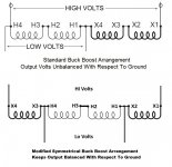
Here's my suggestion to your dilemma.

I'm with JST and SND, you added more impedance, and you unbalanced the input to the Phase Perfect, as compared to your 120/240V service.

A standard buck /boost connection unbalances both voltage and impedance, all of the voltage buck and impedance changes, are placed on one line conductor. With a standard connection diagram. Others have expressed no problem with this arrangement. But your smaller service may not be as ideal.

The transformer connections can be arranged to give symmetry with voltage and impedance with a few small changes in connections. It may be worth it for you to try, and see if it fixes your issue. I have used this connection many times to good effect for sensitive load equipment.

Buck-Boost BalancingConn.jpg

SAF Ω
 
Not that it likely matters now, but I'm with the person who said you should be bucking after the PP and after the on off switch of the machine using 2 single phase transformers and wiring as needed to get the voltage where you want it.

You never mentioned measuring the voltage balance going to your machine. Might have been nice to check that. Also I never heard if you moved the input tap on the control transformer to match your new input voltage. Doubtful if it is the main problem, but just covering all the bases.


FYI - I have both a 3 and 5kva pair of buck boost transformers for sale on this website. I think they're both much bigger then you need, but just to let you know they're there if you ever get thinking you'd like to try again in a different fashion.

Dave
 
Thanks everyone.

The balance to ground was horrible. I think I posted numbers in the thread about installation of the transformer, but I had 120V/98V/195V to ground after installation, versus 118V/122V/208V beforehand. I understand that the high leg will always be there, but that imbalance between the low legs raised an eyebrow (though Phase Technologies said it was fine).

I kept the buck/boost in place and just capped the wiring so I may try rewiring it again but honestly the only reason I was doing it in the first place was I was told it may have contributed to my machine problems and now it looks like that was not the case.


Back
Top