What's new
What's new

Have 15hp Baldor, want to make 3 phase converter

buce

Cast Iron
Joined
Sep 18, 2007
Location
Everett WA
Motor Specs:
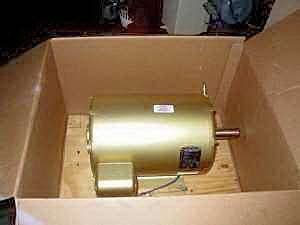
15 HP Baldor AC Electric Motor.
As new condition; in its original shipping carton and bolted to its original wooden shipping base. $375.00
Baldor's elite line of high efficiency motors.
Baldor catalog number EM2513T.
15 HP, 1765 RPM, 3PH, 60HZ, 254T, 3938M, OPSB, F1.
Volts; 230/460. Amps: 35.4/17.7.
NEMA Nom. Efficiency: 93%.
217.00 lbs.
Heavy duty frame; ball bearings; Moisture resistant ISR (Inverter Spike Resistant); copper windings.
Low-loss electrical lamination grade steel.

This will operate in a rural setting at the end of a long street on a single-phase line that supplies 7 or 8 houses. Our shop electrical panel is 200 amp.

We want to be as kind to our neighbors as possible so we are opting for a pony motor start system.

I'm thinking that with a single-phase pony motor we can rig its centrifugal switch to (through a relay) switch power to the coil of the contactor for the 15hp idler only after it is up to speed. Using the auxiliary contacts of either the 15hp contactor or the pony contactor we can prevent both the pony and idler motors from restarting automatically after power outages… which occur frequently in our area. We can also us the auxiliary contacts to turn the pony motor off after power is applied to the idler.

This would give us a single momentary contact push button to turn it on.

My immediate questions are:
What size circuit breaker is needed in our feed?
How many amps should the contactor for the 15hp idler be rated for?
Once it is up and running without balancing caps I would follow the procedure in the Fitch Williams design for a 10 hp converter to add the balancing caps.
What hp rating on the 3-phase output side should we label this thing?

Am I missing things that will cause me trouble?

Thanks in advance
Bruce
 
Is thermal overload protection on the idler necessary or a good idea? If so what amp setting should be used since the motor is only powered via two phases? If it was running on 3-phase I would know the answer.
 
I’m still trying to figure out if the idler needs thermal protection and if so how would one size the cutout amperage.

Any help would be appreciated a great deal!
 
Thermal protection on the idler is a good idea and you size the heaters for the full load amps of the idler just as you would do for a three phase hookup.

I have been working on a circuit design very much like the one describe and have it designed but not built as I have not loacated a cheap 15 hp idler. I plan to build this and demonstrate it at "ArnFest" this year.

I can share what I have if you think it might help. Of course I want feedback on how it works so I can avoid problems.

As already pointed out, you need a 80 amp circuit if you want to run 15 hp of total load. An easy way to size the single phase cirucit is to use 5 amps of 240 volt single phase for each load horsepower. 5 amps x 15 load hp = 75 amps. Your single phase feeders should be 125% of the load so you could use a 90 amp circuit also. A size 3 contactor will handle 90 amps. I usually settle on 80 amps so I can use #4 wire. I may not be able to run the full 15 hp but then I rarely have anything fully loaded.
 
For sure I’ll post pictures and all wiring diagrams.
BaldorGold15hp11.jpg


“size the heaters for the full load amps of the idler just as you would do for a three phase hookup”

So only two heater elements of the thermal protector will actually get used if no load is attached to the output of the converter? And only the current to generate the third leg will pass through these two heater elements.

So would the points of pickup for my newfound 3-phase power would be:
Phase A - after the idler contactor and before the heater element
Phase B - the generated leg of the motor (as it returns back through the heater element??)
Phase C - after the idler contactor and before the heater element

The overload protector that I was thinking of using at
http://factorymation.info/motor_controls/RHN-80.pdf
may not work because I think it has “loss of phase protection” and of course the idler indeed has one phase out.
 
Old style NEMA magnetic starters are the best for RPCs.

First, there are only two overloads.

Second, the overload section is generally separate from the contactor section, thereby allowing capacitors to be inserted AFTER the contactor, but BEFORE the overload, as is required by the NEC (and by common sense).

Third, the unprotected third phase may be "backfed" by the manufactured phase of the idler, so that the starter may serve as both an RPC controller and a disconnecting means for the three-phase "utilization equipment".
 
Thanks Peter,
That helps. I'll look for an old style contactor and hopefully I'll still be able to get 35.4 amp heater elements for it.
Bruce
 
Here is a circuit I have been thinking about for a single button start Pony Motor start 15 Hp RPC. I had to draw this from memory as I do not have my orginal sketches with me. I hope the RPC Gurus here will inspect it with a fine tooth comb. I have not built the circuit so it is not tested but may inspire some innovative thoughts.
Please excuse the lightning bolts i used to represent the motor windings. I do not have a better symbol available right now.

Constructive comments are welcome.
 

Attachments

  • Pony Motor RPC.JPG
    Pony Motor RPC.JPG
    57.5 KB · Views: 49,455
Toolnut,

I'm on the run today but I'll dig into that diagram tonight. The only real problem that I see with both our designs so far is ...

How reliable is the physical connection between the motor shafts? If that connection is lost (broken or slipping belt, lost key or setscrew in love joy coupling, etc.) we have a problem.

Bruce
 
Phase

Buce
The supply is SINGLE phase not 2 PHASE. The rotating motor's armature generates the three phase output. Provide protection for the input based on the normal current draw of the motor.

JRW
 
JRW,

So I’m hearing you say that the two heater elements on the single phase input to the 15 hp idler will indeed protect it in the worst case of power being applied when it is at zero RPM.

Right? With each set to the 35.4 amps of the name plate on the motor.

Bruce
 
I got a pamplet YEARS ago when I first started messing with RPC's. It recommended fusing the input 220 Volt 1 PH power to the RPC at 6 amps/ HP. 15 HP equals 90 amps.

Kent
 
Kent,
So a 90-amp circuit breaker on the supply side would provide that protection. With both a 90 amp breaker and two 35.4 amp (name plate amps) heater elements on the idler which would trip first if the 15 hp idler was at zero RPM when the current hit it? I don’t suppose it matters though.
Bruce
 
WOW,
I am getting my eyes opened also. I have also rounded up the motor (15 hp ) and parts to build a rpc but I only have a 100 amp service in the shop. To top that when I looked at the 16 x 54 lathe that I purchased I discovered that it has a 20 hp motor.
Does this mean that I do not have a big enough service to ever get the lathe turning?
I was thinking I could use the 15 hp rpc to start another 7 1/2 hp motor and then start the lathe.

Richard
 
Ricdel

The fusing is to protect the wiring and components from short circuits. The overloads are to protect the idler from sustained overloads. A common overload rating scheme is the 30 second trip rating which says if the the circuit runs at a 10% overload for 30 seconds the overloads will trip.

To size a single phase circuit you take the total full load amps of all the 3 phase motors that will be running at the same time then multiply this by 1.73. In simple terms this will be about 5 amps of single phase, 240 volt, per load hp. A 20 hp motor would need a 100 amp circuit and it will draw a lot of current on start-up.

The only good reason to use a pony motor start RPC is to limit the start up current draw. I have seen 15 hp RPCs start fine with capacitors when connected to an 80 amp circuit. I start thinking about pony motor starts beginning with 15 hp RPCs. I do not use them for smaller models.

If you have only 100 amp supply to your shop then you do not have enough power available to handle a 20 hp motor. It is also unlikely that you really need a 20 hp drive on a 16" lathe in a home shop. You may be able to change this out for a 10 hp motor and use a 15 hp RPC and be good to go.
 
Buce

The contactor you found will be just about perfect. All you need to do now is procure a seperate overload relay to go with it. It is easier to wire them as seperate components than it is to wire a starter with integral overload relay. Look over the drawing I posted and you will see there are several connections to make between the contactor and the overload relay.
 
Toolnut,

Looking at your wiring diagram, forgive me if I do not understand it yet:

You’re showing a heater element on the manufactured phase. Peter in an above post had implied it was not needed although did not say it was not a good idea to include it.

When you depress your start button the idler motor is denied current until you release it. If your system is up and running and you depress the start button it would remove power from the idler. Why? I would think that if the system is up and running depressing the start button should not do anything at all.

I presume that PR is a potential relay to detect the manufactured leg. Right? When the manufactured leg is then detected the pony motor is turned off. What is the reasoning behind this scheme instead of just using a NC auxiliary contact of M1 to turn the pony motor off? Can’t we assume that the manufactured leg is up if the idler is powered? Does PR prevent a restart of the system until the idler has coasted to a stop?

Is CR1 a relay? You show it at 120 V. Have you already messed with a shingle phase motor to experimentally verify that this setup will trip the relay? I would have thought that it would need a 220 V relay.

Bruce


Back
Top