What's new
What's new

Have a few questions on a VFD for my mill

melsdad

Plastic
Joined
Jan 30, 2008
Location
pennsylvania
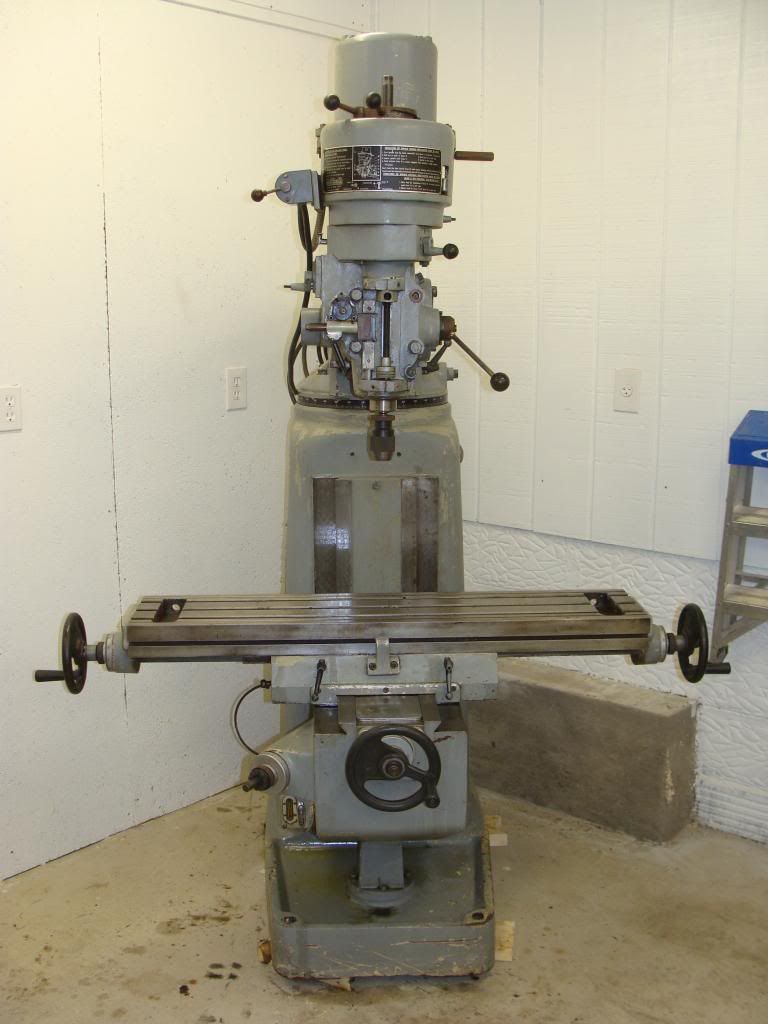
Guys I am looking for some help to power my 2hp 3phase Kent KTM 380 mill. My electrical skills are limited but I can get help from a friend who is an electrician.

I am planning to use this VFD Hitachi WJ200 015SF Variable Frequency Drive 2 HP 230 Vac Single Phase Input | eBay

I would like run the VFD remotely. The drive will be mounted in a control box on the wall, with a small control box mounted on the mill that has a pot, e-stop, and forward and reverse buttons, and possibly a coolant pump switch within easy reach. I will probably mount this on the right side of the knee.

My questions are:

1) Is this a quality VFD, and the correct one?
2) where do I get the other electrical components....pot, e-stop, forward-rev. buttons....etc?
3) How do I know which components are correct...voltage wise?

I am certain I will have more questions as this project progresses.

Thanks in advance for the help!!


the vfd is a good one.
the pot etc can be gotten at radio shack, mcmaster carr, allied electronics, Mouser, etc, etc. nothing special.

the control voltage is 24 volts.
the
 
The manual for the controller will tell you what the voltage is, 12 or 24 most likely. It's super low amperage as it's only sending a signal so I used Cat5 networking cable. Pretty much any switch is going to work because of the low amperage unless you were using some sort of circuit board.

I managed to find a used panel on ebay for some random machine and used the switches and buttons off that. I paid like $30 shipped and they were good quality and full size instead of buying little toggle switches and buttons at Radio Shack.

You'll be able to look in the manual and see what it's looking for. Mine is "if this wire has no signal, go forward, if it has signal, reverse." So I could just use a simple on off switch for that.
 
Also, just for safety, disable the drum switch on the left side of your motor or, better yet, bypass it altogether. If someone comes into your shop and decides to use that switch to change from forward to reverse, as it is no doubt labeled, they will fry the VFD instantly. You wouldn't do that. But your well-meaning brother-in-law might.

Denis
 
I've got a similar Hitachi VFD drive on my mill and I liked it so much that I put one on my lathe, too. I bought most components on Ebay, but you can find good parts at Digi-Key or Allied, as well. I don't like RadioShack for stuff like that.

I added a 'Tachulator' to my panels that read out in RPM or SFM. Trexon Tachulator Digital Tachometers

There is a section of PM that is dedicated to VFDs and RPCs.

The biggest problem with the Hitachi is learning how to program it. The book isn't straight-forward, you'll have to search in several places and take notes to get it figured out.
 
Also, just for safety, disable the drum switch on the left side of your motor or, better yet, bypass it altogether. If someone comes into your shop and decides to use that switch to change from forward to reverse, as it is no doubt labeled, they will fry the VFD instantly. You wouldn't do that. But your well-meaning brother-in-law might.
Denis

Impressive.....

But not true.

I mean the frying, not the bro-in-law.... HE might do that, but it won't fry any half-way decently designed VFD, and the Hitachi is decently designed... it's a good unit. I'm not entirely sure how to design one that WOULD be instantly fried that way, since the VFD turns off (and on) it's own output several thousand times per second......and does it a good bit faster than the switch would.

It's an old warning, that probably had some validity with ancient VFDs using transformer driven bipolar output devices.

But while you CAN turn the thing OFF with a switch, a 2HP VFD wiill not do well trying to start a 2HP motor that has been "dropped onto" the line by a switch, to start it. You'd need more like a 15 HP to attempt that, because of the motor's starting current surge.

So yes, do use the VFD controls. But if the bro-in-law manages to do something silly, it likely won't fry the VFD.

The only silly thing my 2 bro-in-laws did was to get fired by their wives before they had a chance to mess up anything in my shop. (Getting well corned every night and passing out on the front lawn, yours or the neighbors, will have that effect on wives.)
 
If you would rather spend a few more dollars and get excellent phone support and selection advice and a very nice robust VFD with an accessory remote that has a RPM, amperage etc readout right on it, consider Automation Direct. Drives | AutomationDirect.com I have purchased two of their VFD's and have been well satisfied.

I have known of people who bought eBay drives from offshore with very poor documentation and no support that gave up in frustration. Not saying that many many people have not been able to jump that hurdle, especially with the excellent support available from PM.

I have no connection to AD whatsoever other than being a happy customer of their US-based distribution center.

Denis
 
Impressive.....

But not true.

I mean the frying, not the bro-in-law.... HE might do that, but it won't fry any half-way decently designed VFD, and the Hitachi is decently designed... it's a good unit. I'm not entirely sure how to design one that WOULD be instantly fried that way, since the VFD turns off (and on) it's own output several thousand times per second......and does it a good bit faster than the switch would.

It's an old warning, that probably had some validity with ancient VFDs using transformer driven bipolar output devices.

But while you CAN turn the thing OFF with a switch, a 2HP VFD wiill not do well trying to start a 2HP motor that has been "dropped onto" the line by a switch, to start it. You'd need more like a 15 HP to attempt that, because of the motor's starting current surge.

So yes, do use the VFD controls. But if the bro-in-law manages to do something silly, it likely won't fry the VFD.

The only silly thing my 2 bro-in-laws did was to get fired by their wives before they had a chance to mess up anything in my shop. (Getting well corned every night and passing out on the front lawn, yours or the neighbors, will have that effect on wives.)

What you say may be true. If you have a lot of experience with doing this and it has not hurt your drive, I stand cautiously corrected. I still would not try it with my unit. From AD's current manual, page 2-6, on thier GS-2 drive:http://www.automationdirect.com/static/manuals/gs2m/ch2.pdf
"5. Do not use a power circuit contactor or disconnect switch for run/stop control
of the AC drive and motor. This will reduce the operating life cycle of the AC
drive. Cycling a power circuit switching device while the AC drive is in run
mode should be done only in emergency situations." (I added the red.)

Denis
 
Last edited:
So, JST, could you kindly provide some basis for your assertion? I would be more inclined to accept it as fact if you could provide some reason to back it up, especially since it seems to contradict the manufacturer of the device in question. Your statement that the unit cycles on and off at high frequency may not be the same as interrupting the power supply to a 2HP motor running at speed completely and suddenly. I am wondering about voltage surges that might be induced in such a case. But then, I am certainly not an electrical engineer. And since I am not, I tend to follow the manufacturer's recommendation until proven otherwise.

Denis
 
One word of general caution: don't go ONLY by HP ratings, double check the motor nameplate FLA against the rated output current of the VFD you want to buy. All motors are not created equal.

Re: my opinion/rant on "switch or not":
The issue JST is referring to is, MOST new modern small to mid-range VFDs now use what is called an IPM (Intelligent Power Module) to handle both the input and output power flow, in other words the rectifier diodes and the output transistors, ALONG with much of the firing circuitry of the transistors, are all neatly packaged together as a single "block" that is about the size of a credit card only thicker. In that device, the firing and protection of the transistors is all prepackaged. With modern IGBT devices, the controls to accomplish that firing are done digitally, instead of with analog based systems of old that were used on what were called "darlington transistors". For the most part the way darlingtons were fired made them too slow to avoid being damaged by steep rises in current, referred to as dI/dt (d for delta or change, I for current, t for time, so dI/dt means a high rate of change in current). However nobody is using darlingtons for small drives anymore, the IPM has made them obsolete. In the latest 5th generation IPM designs (circa 2012), they have very extensive protection strategies for the transistors that will resist MOST of the rigors of having a set of contacts opened on the circuit while running. In the old darlingtons, the possibility of instant death was very real. Now, not so much.

BUT, I for one do not trust it completely. The protection designs were implemented to help protect the IGBTs from short circuits and ground faults on the output, not from dV/dt, or high VOLTAGE change rate, that takes place as switch contacts open and an arc is created. True, MOST of the potential damaging effects of that arc are basically the same as a short circuit, steep rise in current, and the IPM mfrs state that the protection offers "side benefits", but that was not the original intent. In other words they were not TRYING to solve that dV/dt problem, it just appears that it came along for the ride when they solved OTHER problems.

I will admit that I can't say I have seen transistor damage for a while now, but I still feel it's prudent to not take chances. The best developments in IPM protection technology are not really that old, 10 year old IPM designs didn't have them at all, and the latest level has only been out a year, with the marketing spin claiming how much better it is than OLD versions, which for them means just Gen 4! (although Gen 3 and 4 were still pretty good). Add to that the fact that when people in this particular forum are looking at VFDs, there is no telling what they are buying, old or new, and I still think opening switches below running VFDs should be avoided in all but emergency situations, an opinion shared by most VFD mfrs.
 
For mill equipped with a drum switch I prefer to re-purpose the drum switch as the VFD control. It provides FWD, OFF, and REV. You would only need to add a potentiometer . I have been using my mill for years with this setup and it works great. For clarity: I connect the VFD directly to the motor and rewire the drum switch to the VFD control terminals. I also install a single phase fused disconnect before the VFD so I can turn off power to the VFD.
The Hitachi WJ200 is a fine VFD but it is hard to find what you need in the manual. The manual included is a quick start up guide (about 98 pages) and a CD. The full manual is likely on the CD but I downloaded one from a dealers website and have been using it. I just finished installing a WJ200 in the method the OP first described and it took me 3 trips to the job site before I managed to find all the codes I needed to get it to work on 3 wire control. Now the customer suddenly decides he has to use the mill for tapping and he did not buy a braking resistor. Problem with the Hitachi manual is it has a section for 3 wire control but leaves out the basic step of setting the VFD to display ALL of the codes. This has to be done before one can get access to the menus/codes needed to setup the 3 wire control. If one uses the drum switch, it is maintained control and not 3-wire so it is much easier to program as the codes are available in the default menus.
The Automation Direct VFDs have a simple manual and are much easier to program however they do not have the capabilities of the Hitachi WJ200 but they are entirely satisfactory for a mill as long as one gets a Sensorless Vector model.

I think the general concensus in these parts is that repurposing the drum switch as a VFD control interface is the way to go. It keeps the controls looking and feeling like they did, which is important in many cases. I just did one like that though and a small word of caution. Those drum switch contacts tended to get abused in switching, or rather "plugging" the motors if they were directly connected, so they are often in poor shape and very dirty. The VFD input signals are very low voltage and subject to circuit resistance, i.e. dirty and burned contacts. So when repurposing, see if you can open the switch and clean the contacts as much as possible. We had issues at first, but nothing that a can of CRC contact cleaner couldn't cure.
 
I've got a similar Hitachi VFD drive on my mill and I liked it so much that I put one on my lathe, too. I bought most components on Ebay, but you can find good parts at Digi-Key or Allied, as well. I don't like RadioShack for stuff like that.

I added a 'Tachulator' to my panels that read out in RPM or SFM. Trexon Tachulator Digital Tachometers

There is a section of PM that is dedicated to VFDs and RPCs.

The biggest problem with the Hitachi is learning how to program it. The book isn't straight-forward, you'll have to search in several places and take notes to get it figured out.

I like the looks of the tachulator! I was wondering how I can integrate that into my system.
 
From what I understand I would benefit from going up to a 3hp VFD for my 2hp motor.

Any thoughts on this?

I had been waiting for some of the real experts to weigh in on this. But, I think the answer is a pretty straight forward 2HP VFD for a 2HP mill. It is common for people to use a larger RPC, say 130 to 150% the size of the motor they anticipate to run. A call to customer support at the company I mentioned above would provide a very authoritative answer.

Denis
 
I've got a similar Hitachi VFD drive on my mill and I liked it so much that I put one on my lathe, too. I bought most components on Ebay, but you can find good parts at Digi-Key or Allied, as well. I don't like RadioShack for stuff like that.

I added a 'Tachulator' to my panels that read out in RPM or SFM. Trexon Tachulator Digital Tachometers

There is a section of PM that is dedicated to VFDs and RPCs.

The biggest problem with the Hitachi is learning how to program it. The book isn't straight-forward, you'll have to search in several places and take notes to get it figured out.

Thanks for the link to the tach!
I am planning a refit of a little Hardinge horizontal with my first play with VFD so that I get variable speed, and I love the idea of the built in tach!
 
I think the general concensus in these parts is that repurposing the drum switch as a VFD control interface is the way to go. It keeps the controls looking and feeling like they did, which is important in many cases. I just did one like that though and a small word of caution. Those drum switch contacts tended to get abused in switching, or rather "plugging" the motors if they were directly connected, so they are often in poor shape and very dirty. The VFD input signals are very low voltage and subject to circuit resistance, i.e. dirty and burned contacts. So when repurposing, see if you can open the switch and clean the contacts as much as possible. We had issues at first, but nothing that a can of CRC contact cleaner couldn't cure.

If one were looking for said drum switch, where would one look?
 
Nothing wrong with following the maker's recommendations atall.

Wouldn't take a great deal more time to track a few of JST's contributions on PM.

His credentials are already 'provided'.

;)

Credentials and contributions are a wonderful thing. They do not make the bearer of those credentials immune from error or beyond questioning of an assertion they may make. They should not expect to not be questioned. And, given their evident capabilities it should be simple for them to satisfactorily explain their statements. Citing their credentials does not accomplish that goal.

I remain unconvinced given that the several VFD manufacturer's current online manuals (Hitachi being one of them BTW) all advise against interruption of power provided by a VFD to a motor with such an interruption to be done ONLY in emergency circumstances.

My thanks to Jraef for taking the time to provide lucid and useful insight into VFD construction and safety features that they contain.

It would be interesting to hear from someone who has accidentally or intentionally interrupted the connection to a VFD while operating a motor. How did that work out? Maybe it was OK. Anybody want to try it with their VFD?

Denis
 
That is presumably a sort of "boilerplate" in the manual....

1) Experience... A very large number of inverters, which are made essentially in the exact same way as a VFD, are made and sold for "off-grid" applications.

Absolutely NOBODY turns them off, plugs in a device, turns it on, and then carefully switches the inverter on. NO. Loads are 'dropped-on" to the output willy-nilly, and switched off whenever needed. The inverters survive for years, and are neither damaged nor degraded. And there is no theoretical reason why they should be.

2) Theoretical reasons. The output section, whether it is an IPM as jraef describes, or a standard 3 phase full bridge, discrete, or packaged..... it will have, for each IGBT, an "antiparallel" fast recovery diode.

When the current, say from the upper device, is interrupted by any means, it does not instantly cease. There is energy in teh load inductance, which causes the driven end of the output to "fly negative", to the negative "rail" or power supply source. At that point, the anti-parallel diode begins to conduct, and the voltage is "clamped" the the negative rail. If there is no further switching, the energy in the load inductance will be dissipated in charging the bus, and in the load resistance.

This happens at all currents, from minimum to maximum, and at all polarities of output, several thousand times per second. That is a designed-in and intended mode of operation, the diodes are sized and intended for the purpose.

When the output is switched off, that adds a few more transitions, as the switch "bounces" and then the circuit is open. The energy of the last pulse is dissipated and all is well.

With OLD VFDS, the "fast recovery" diodes may have been slower. They also may not have turned "on" as fast. There is a "forward" current delay in conduction as well as a recovery time (the time for the current to decay when polarity is reversed.)

That slower "turn-on" might have allowed transient voltages above the bus. If there was any oscillation due to the "bouncing" of the switch, the turn-on and turn-off could have driven up the dissipation in a slow diode during the switching event.

Those old VFDs had slower transistor switching times that didn't stress the slow diodes, and operated at a low PWM frequency, often just a basic 6 step. They might not tolerate switching off by an external switch very well. usually they were rather "close to the edge" in design.

Virtually any modern unit is made with faster devices, frequencies up to 32 kHz, and will not be bothered.

BUT, as I said, there is no advantage to the switch, since you generally cannot turn the motor ON again with the VFD running. THAT will stress the overcurrent circuits, essentially "testing the parachute" every time you do it.

With a large enough VFD, you can do both on and off switching, without problems.

3) Phase perfect..... just a big VFD.... which you treat the same as any power line... drop motors on, turn them off, whatever

I have posted this before, but here is a typical module, NOT an IPM, just an older rectifier and output device module from Fuji. You can see the IGBTs and the antiparallel (flyback) diodes. I have no clue what die were used in this, but the VFD it is out of has either a 16 kHz or a 32 kHz max PWM frequency choice.


Back
Top