What's new
What's new

Help Needed, 2HP Bridgeport Series 1 CNC Anilam Crusader M 440 vac to 230 vac

r1elkins

Plastic
Joined
Apr 2, 2010
Location
Berthoud, CO
Hello Everyone.

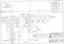
I just received a new to me 2HP Bridgeport Series 1 3-axis CNC fitted with Anilam Crusader Series M controller. It is currently wired for 3 phase 440 volts. Looking at the Anilam wiring diagrams, I believe I can rewire it run off of three phase 230 volts. The spindle motor can also be rewired for 230 volts as well. My shop has single phase 230 volt service. My initial thought is to use a VFD to provide the 230 volt 3 phase service, after I rewire the Anilam Crusader controller and the spindle motor for 230 volts. This will eliminate me from having to buy a step-up transformer. I have attached the wiring diagrams that came with this unit, I highlighted the areas I think I need to rewire. I have an Optidrive E3 2HP VFD I want to use to power the unit, but I'm not sure it's big enough. The Crusader M controller operates off 110 volts. I have already turned it on and verified it works (powers up at least). As an alternative, I've been looking for a step-up transformer on eBay just in case this is not recommended, however, I'm not very familiar with what to look for. This option would have me step up my single phase voltage from 230 to 440, then use a VFD to create the three phase 440 volt service. This option requires I buy a transformer and another VFD. Any advice you can give would be appreciated. I'd really like to know what I'm doing before I go cutting jumpers. Thank you, Jason. Page 3.jpgPage 2.jpgPage 1.jpgPage 4.jpgPage 5.jpg
 
So I think I might be confusing myself. I think the Crusader M controller is completely powered via 115 vac outlet. I think because there is a sticker on the cabinet door that says 440 Volts, I assumed the controller was wired for 440. But, I think that is not the case and the 440 Volt sticker does not apply to the controller, only the spindle motor. I busted out the volt meter and was checking know power sources and was getting the correct values. I think this entire thing is wired from 115 vac. And I think the section where it talks about "Wiring for 230V" isn't to step down the voltage from 440, it's to increase it from 115. Point is, I think I was assuming the Crusader M controller is wired for 440 volt when in fact it's wire for 115. I'm going to wire up my spindle for 230 volts and then hook up my VFD. I think that is all that is needed to run this machine. Please correct me if I'm wrong.
 
So I got it powered up. But every time I manually turn the spindle on, I get an over current fault. The only way to power the spindle is to turn it on at the spindle, then turn on the VFD. That allows it to ramp up the power. I'm not optimistic my VFD is powerful enough for this motor. I'm done for the night, but more troubleshooting is in order.
 
Generally you want nothing between the VFD and motor, or only safety disconnects.

You need to start the VFD with the motor connected, as the VFD cannot supply starting current; it has to ramp the motor up.

The VFD also needs to only supply motor loads as the variable-voltage variable-frequency supply doesn't play nicely with things like contactor or brake coils.

Thank you for the info. This makes a lot of sense. I think I can rewire the existing spindle forward/reverse switch to toggle power at the VFD. I could potentially have the Anilam Crusader M controller control the spindle power via the VFD. But that's TBD later.

Right now I need to get the Crusader M controller working. Unfortunately one of the circuit boards has a blown capacitor, PCB513 Rev D 901-165. See attached image. I have a replacement board, but it's a newer revision, Rev F. I tried swapping it out, hoping it would be backwards compatible, but it did nothing. The good, spare board I have is a Rev F, and the bad board is a Rev D. I am going to try and remove all the EPROMs from the Rev D and install them onto the Rev F board. Maybe I get lucky and that will make the board compatible. There's 2 jumper wires I need to install on the backside of the board as well. See pictures for what I'm talking about.

20200925_103817.jpg20200925_103829.jpg20200924_122649 (1).jpg20200925_103914.jpg20200925_103857.jpg

Anyone have experience doing this? Or know of someone I can reach out to for support? CNCrepair.com said they think they could fix the board but it would take 4 hours. At $150/hr, that's not a cheap fix.

Thoughts?
 
Are you sure it was cap and not an MOV?
$600 for a capacitor replacement I hope I am wrong.
Also the question that should be asked is: Did the cap blow into low earth orbit due to it failing of own accord or was it an innocent bystander Sometimes the blown to bits component is only a symptom of the real problem.

I thought the same as you, $600 was expensive for such a simple job. I called a local electronics repair shop and took it to them. They think the voltage regulator next to the capacitors/varistors blew up. They said it should be a fairly easy fix. And at $60/hr, I'm happy to pay them. I'm guessing it'll be a week before they can touch it. I'm optimistic this will work.
 
So a quick update, I have the board fixed and it appears to be working. The issue I'm having now is I am getting a SERVO DISCNT error every time I try to move the table. If I do it manually, I get the error message. If I write a program and run it, I get the same error message. I get this message for all three axis, in all directions. I looked through the manual, but it doesn't really give much info on this error. It basically told me to call Anilam tech support. Anyhow, I went through the diagnostics and there were no errors. Anyone have any advice? I've search the forums but couldn't find any definite troubleshooting steps. Thanks in advance!
 
Are your servo amps powered up?
perhaps they also need 3 phase
3 ~15 amp servo drives is alot for 120 volts

So everything inside the cabinet is running off 120 volts I think. From what I can tell, only the motor is three phase. Sorry if this is a stupid question, but how do I tell if the servo drives are powering up?

Two other things to note, though I'm not sure it matters: 1. I get a SERVO LAG error when I manually crank on the servos. 2. Under 68000 Diagnostics, it fails the Durat test...I have no idea what that is.
 
Looking at the wiring diagram I posted above, it looks like the servo drives are powered with 15VAC. Also, the data plate on the side of the servo states 5.8 amps continuous, 30 amps peak, max voltage 140 VDC. So I feel pretty confident they do no require three phase power.
 
I could not take the time to zoom in and research those

Usually there are some LEDs lit up maybe even with labels

Thanks and no worries. I think I might have found part of the problem. Starting at the servos, I looked for 140VDC at the harness. I got nothing. Following the wiring diagram all the way back to PCB 801, it appears that P6 does not have any line voltage. The fuses are all good, and I'm getting 115VAC at the fuses. So whatever is supposed to be powering P6 is not working. This makes sense, because the hour meter is tied to P6, and it hasn't moved since I bought the thing. I'm going to try and find a circuit board diagram for PCB 801 and figure out why P6 is dead.


Back
Top