What's new
What's new

help w/ wiring 3ph motor missing diagram (need 240v delta)

venison

Plastic
Joined
Nov 15, 2016
I acquired an old GE motor that is missing its wiring diagram.
GE5hp (Medium).jpg

have an American Rotary PC which puts out Delta voltage.

I've read through this post: https://www.practicalmachinist.com/...s-and-vfd/9-wire-3-phase-motor-wiring-102888/

I believe my wiring should be:
L1--1,6,7
L2--2,4,8
L3--3,5,9


but I'm not sure. Don't really understand the whole Wye/Delta thing... There's the power supply, how the motor is wired, and how the motor is built... So a motor can be built and/or wired for either delta, wye, or either??

How to know w/o wiring diagram?

"Determining wye or delta connection for motors
On delta connected motor lead #s (7,8, & 9), (1& 4), (5& 2), (3& 6) have continuity with each other
On wye connected motors (1,4& 9), (3,6 & 8), (7,2 & 5) have continuity with each other."?

Thanks very much.
 
sorry for double post... 1st one was lost in cyberspace for a while then showed up after I posted again...
 
Study the diagrams carefully and test each wire for proper continuity and it should become apparent which you have. Then once you have that, connect the motor per the diagrams, then test again and each leg to another should all test the same. Typically, if you have it wrong, you will know it but take your time.

I am assuming your leads are numbered. If that, that is more work but doable. I releaded a 12 wire motor years ago where someone chopped them all off. Still running......
 
For a correct diagram see a post below titled "wiring motor to VFD question".

The motor can not be wired "wye". It has two different wiring choices based on whether you are using 220 volts or 440 volts. Whether your source is wye or delta, the motor will always be configured as a delta.

Do a google search for "9 wire motor connection diagram" and you will find many instances of the same chart as cited in the post above.
 
I deleted my earlier post. First all wires must be disconnected to check continuity. If its 1-4, 2-5 and 5-6 that have continuity but not to each other and 7-8-9 have continuity to each other it is a Wye motor on the other hand if you have 1-4-9, 2-5-7 and 3-6-8 have continuity but not to each other you have a Delta wound motor. I.m not sure what kind of motor is shown in the stated reference but that's an odd European motor and the connection for low voltage is an odd delta wye. Most US made motors for low voltage will be connected 1-7, 2-8 and 3-9. 3 phase power is connected one line to each of the jumped pair. 4-5-6 will just be connected together. If you have wye. If as I assume you have the wires marked and no diagram then determine if you have either Delta or a Wye motor. Low HP motor are usually do not have start and run connection, if so they will be 6 or 12 wire motors. US motors don't combine Delta and Wye they are one or the other. That is unless they are made for some special application.
 
ok, so just to reiterate, I do not have a wiring diagram for the motor I am asking about. I only have the plate shown in the pic. It's a GE, made in USA, dual voltage 208-220/440, 5 hp, 9 wire; leads are numbered 1-9.

My phase converter puts out Delta, low (240v) voltage, which is what I want to power the motor with.

posts 3 and 4 above tell me to look at the diagrams... I did a search and found the thread referenced in post 4 titled "wiring motor to VFD question", which shows a diagram for a German made Siemens motor.
https://www.practicalmachinist.com/...n-360944/?highlight=wiring+motor+vfd+question


I have a number of other three phase motors with diagrams as well, I just don't have the diagram for the GE that I'm asking about.
From reading posts 4 and 5, it sounds like some motors are Wye and some are Delta, but all are connected to their power source in a delta configuration?? ("Whether your source is wye or delta, the motor will always be configured as a delta.")

Still not really following how that works, but I looked at my other diagrams and others online. It looks like I send line voltage to L1(1,7);L2(2,8);L3(3,9)and bond 4,5,6, as mentioned, but I will do the continuity testing to be sure.

Thanks again!
 
You just need to follow my advice and tone the wires to determine what you are working with. As far as what kind of power you provide the motor, that matters NONE!

You can have 240/120V power, which is delta, and 208/120V which is wye, and they will BOTH power a motor the same aside the voltage difference. Don't concern yourself with that. You are not powering a motor with a neutral connection.

if the motor leads are numbered, tone them, then study the diagrams to determine how the windings are configured. You are over thinking it.
 
Again How power is delivered either from a VFD or transformer means nothing to the motor. Voltage, Phase and Amps is all it requires. Check continuity as I mentioned either by tone devise, light, digital or analog meter BUT check continuity to determine how your motor is wound. Again it makes no difference how it's wound but it dose make a difference in connection for voltage. So before making any connections you must find out if you motor is wound Delta or Wye. Then check NEMA wiring of American Motors. That Siemens Delta motor is an odd configuration and might be because of the power differences in Europe. That wiring for low voltage shown in the Siemens diagram low voltage will create a combination of Delta and Wye. I have not seen that combination used in American made motors. They are either all Delta or all Wye when voltage change is wired. For high voltage the coils are put in series, low voltage in Parallel and both types must be in the correct order.
Just to make things clear Delta supplied power will run a Wye wound motor as well as Wye supplied power will run a Delta wound motor! Also you are not going to simply take a Wye wound 9 wire motor and change it to Delta or the other way Delta to Wye.
 
ok, I did some continuity testing and found the following:

1&4; 1 ohm
2&5; 1 ohm
3&6; 1 ohm

7,8,9; 2 ohms

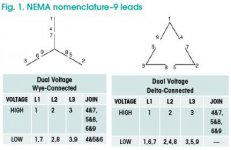
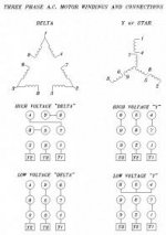
Based on these diagrams, I would think that this is a Wye wound motor, is that right?
deltawye.jpgwyedelta.jpg


Apologies for being so slow to grasp all this. I think I am starting to understand a little better, but I'm still confused as to the relationships between the supply (in my case, 240v delta from a rpc - delta doesn't matter here, only that it is 240v?), in what way L1,2,&3 are wired to the 9 leads (does matter - must be connected in correct sequence for low voltage?), and the way the motor is built (for this motor, wye wound?).

If I understand correctly (looking at 240v only) I could power the motor in wye configuration by connecting
L1 to 1&7
L2 to 2&8
L3 to 3&9
and join 4,5,&6?

Or in delta where

L1 to 1,6,7
L2 to 2,4,8
L3 to 3,5,9?

Again, sorry for being so slow... This stuff is all new to me and not entirely intuitive.
 
1) Again, the SOURCE configuration being Wye or Delta is TOTALLY IRRELEVANT. Pay ZERO attention to that and move on.

2) 99.99999% of "9 lead dual voltage" motors made for the US are going to have the EXACT same connection patterns depending on whether they are internally connected as Wye or Delta, which is a decision made by the motor manufacturer based on manufacturing considerations. At 5HP and below, because there is less room in the frame and slots for the windings, most motors are Wye wound because you need less wire (58%) for the same power rating. The connection patterns then are a NEMA (National Electrical Manufacturer's Assoc.) standard.

3) So the diagram you have already posted is the correct one and your assessment of which leads are which not only confirms that it is Wye wound, but that you are correct in how that gets connected. The only remaining issue is the rotation, and you cannot tell what that's going to be in advance, so keep in mind that if it spins the wrong direction, you simply swap any two of the incoming lines, i.e. L1 and L2.
 
Jraef is correct. You did your home work and determined the motor was Wye wound. You also located the typical wiring diagram for 9 wire US motor Wye wound. Make the connections and power it up. If it runs the wrong direction reverse any 2 of the 3 input wire connections as Jraef stated and your good to go! Good job!


Back
Top