What's new
What's new

Help wiring single phase 110v motor to drum switch

bodaver32

Plastic
Joined
Aug 8, 2011
Location
Indiana
Folks,

Can you help? I will be the first to admit I am inept on the electrical side of things past basic home wiring.

I have done internet searches and just get more confused.

I am fabricating a project and want to put a 110 single phase motor on a drum switch so that I have the capability of reversing it.

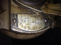
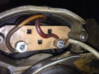
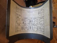
Below are the photos of the switch diagrams, motor wiring diagram and the motor terminals.

Also, I opened the motor up to get an idea of where the wires come from and go to, but please bear with me as my descriptions are elementary.

There are 4 wires coming from the windings:

Orange = from the windings to a points switch. When switch is closed (?) the switch completes the circuit and the wire goes to the "low" terminal post. When the switch is open (?) it completes the circuit to the light blue wire, which goes to the "high" terminal post.

Black = from windings to a points switch. The switch completes the circuit when it opens/closes. This goes to the "low" terminal post.

Yellow = from windings and goes directly to the "High" terminal post.

Red = from windings to the "com" terminal post.

Many thanks for any help!

Greg

110_motor_wiring_diagram.jpg


Internal_connections_drum_switch.jpg


Drum_switch_diagram.jpg


110_motor_wiring_v2.jpg
 
This is probably a split phase motor and the red and black leads are the starting winding. The situation is complicated by it being a two speed motor. All Google tells me is that various dealers have them for sale- no more information that what is on the label. First you should be aware that it probably will not reverse when running. You have to let it come to almost a complete stop for the starting winding to re-engage. Otherwise, it will just keep running in the same direction. There is a discussion here

http://www.practicalmachinist.com/v...elp-can-i-modify-motor-fwd-rev-switch-277436/

Can you post a picture of the drum switch with the cover off?

Bill
 
It is easier for me to study the internal workings of a drum switch than to understand the typical diagram.

And since many of the diagrams are missing, understanding the theory of the switch is helpful.

The OP hasn't mentioned use of HI/LO, but if that is desired, the easy/low cost way to do that is to purchase another drum switch and let one drum switch handle the forward/reverse and the other handle the HI/LO.

Let's focus on "INTERCHANGE RED & BLACK":

Obtain additional red and black wire in adequate guage. How far from the switch to the motor? Double or triple that distance and get that amount of red and that amount of black.

Create pairs of Red wire and pairs of black wire, from motor to switch.

Remove the Red wire from the terminal board and splice it onto one end of one of the Red wires.
The other end of this same Red wire is connected to terminal 1 of the drum switch.


Remove the Black wire from the terminal board and splice it onto one end of one of the Black wires.
The other end of this same Black wire is connected to terminal 4 of the drum switch.


With the remaining pair of Red and Black wires:

The Red wire is connected to motor terminal 4 and the other end is connected to drum switch terminal 2.
The Black wire is connected to motor terminal 2 and the other end is connected to drum switch terminal 3.


Okay, that accomplishes the reversing function.

Can you figure out to how to energize the motor with the drum switch?

When the wiring is completed, you will have a total of seven wires running to the motor (unless you wire it for HI/Lo, then you will have eight wires).
Can you tell me what colors, and how many of each color?

Some hints:
Green is Ground.
Black is "hot".
White is Neutral.
 
The challenges keep coming as I discovered that the "Powr-Kraft" (Montgomery Wards) 1/4 HP 1725 RPM Split Phase motor that came with the lathe was missing the "drum switch" to allow forward and reverse. So I bought a Dayton (2X441A) drum switch, and see that my motor only has two wires, and the back of the motor mentioned "switching polarity of the wires to reverse direction.

Hum, this seems simple enough, but I'm once again hoping someone has the wisdom to make sure I don't fry the motor (or myself!).

I read about how to set this up IF my motor had 4 wires to set-up, but it does not (see photos). I appreciate the help and will make sure to post the results once I figure this out. Thanks in advance.IMG_1827.jpgIMG_1828.jpgIMG_1832.jpgIMG_1834.jpgIMG_1836.jpg
 
This can be done, but you will have to open the motor up. And you need to understand there is a run and start winding, and create separate leads, so you have 4 connections.
This is a good time to clean the bearings and grease them.
Pull the end cap (bell housing) off the motor, trace where these 2 wires go. They should split from one wire to two. That's where you will break them apart and bring out 2 new connections. One pair for the run winding, and one pair for the start winding.
 
Lo7us,

Follow the diagram on your drum switch for the "Split Phase" connection. Your motor uses red and yell for the start winding, as shown in your photo. The other two wires for the run winding are directly connected under the binding posts of the terminal board.

To reiterate the posts are the run winding, the yel & red are the start. Run all four out to your drum switch and connect per the diagram. Reverse one pair of the motor windings if it goes the wrong direction according to the label.

SAF Ω

Thank you - I successfully completed attaching my drum switch using the attached wiring diagram (for split phase) and once I discovered that by detaching the two wires (that the back of the motor said to switch to change direction) I had the needed 4 wires as indicated in the diagram.

I hope this helps.

Single_phase_drum_switch_wiring.jpg


Back
Top