What's new
What's new

Hitachi WJ200 Question

atomarc

Diamond
Joined
Mar 16, 2009
Location
Eureka, CA
I'll pose this question even though the problem has seemed to have 'self healed'..how, I have no clue!

Hitchi WJ200 1hp drive with a external 200 watt-100 ohm braking resistor. This is on a small CNC machine that has several hours under its belt and stops instantly when commanded to.

Today the machine was fired up and the spindle run for approximately 15 minutes whereupon a burning- electrical smell was noticed. Investigating, the externally mounted braking resistor was found to be hot enough to burn your hand.

When disconnected it showed 'good' but the connection to the drive would show anywhere between 50 volts clear up to 300 volts and then trip on a braking module fault code.

All braking parameters were the same as they had always been from day one.

All brake functions were disabled and the trip did not return.

The connection from external resistor to drive was checked again and showed no erratic voltage so the resistor was reconnected and braking parameters were set to their previous values.

The spindle again stops instantly, no faults and the external resistor is as cool as a cucumber.

The drive has not been powered for several weeks but it resides in a sealed enclosure in a dry shop environment.

How can a solid state device like a VFD go nuts, then be OK?

Needless to say we are going to keep an eye on the braking resistor.

Any wisdom from the EE gurus!

Stuart
 
I obviously am guessing, or really, reciting possible reasons that might apply.....but that I have no idea if they really do in your case.

1). Temporary high voltage condition of power line that triggered the resistor 'on'. The circuit really reacts to high bus voltage, and does not 'care' why it is high. You may want to set the trip voltage higher, there is , IIRC, a setting for that. You REALLY do not want any allowable bus voltage to trip the resistor 'on'. Set it to something over 400 V, maybe 425V or nearly as high as it can be set.

2) Possible EMI or 'noise' on the mains that temporarily 'scrambled the brains" of the VFD and made it set the brake resistor 'on'. Problem went away when 'reset'.... typical of that sort of "soft failure", where settings get scrambled, but there is no 'hardware damage', no shorted IGBT, etc.

Probably there are other possible causes.
 
Thank you JST..those scenarios sound plausible..I guess. Being a solid state device it seems nothing could get 'stuck', and it works perfectly right now so I guess nothing got fried so it looks like we're back in business for the time being.

Stuart
 
Do check the voltage setting and make sure it is higher than the power line peaks.... that is the most likely, I think.
 
I obviously am guessing, or really, reciting possible reasons that might apply.....but that I have no idea if they really do in your case.

1). Temporary high voltage condition of power line that triggered the resistor 'on'. The circuit really reacts to high bus voltage, and does not 'care' why it is high. You may want to set the trip voltage higher, there is , IIRC, a setting for that. You REALLY do not want any allowable bus voltage to trip the resistor 'on'. Set it to something over 400 V, maybe 425V or nearly as high as it can be set.

2) Possible EMI or 'noise' on the mains that temporarily 'scrambled the brains" of the VFD and made it set the brake resistor 'on'. Problem went away when 'reset'.... typical of that sort of "soft failure", where settings get scrambled, but there is no 'hardware damage', no shorted IGBT, etc.

Probably there are other possible causes.

Rebuttal:

1. The device is doing what it was designed to do. The maximum power calculation should not be any higher than 395V for 240VAC. Any higher and hope your little drive can take the stress.

2. Terms like "scrambled" might apply to a bug in the firmware. A nice way to wash away the real problem or real issue.

Selecting a brake resistor needs:
- motor name plate power
- motor name plate speed
- decel time
- motor inertia and load inertia
- motor shaft speed, torque, power profile of the drive

Just sticking in a resistor because it sounds like it should work is not correct.
 
Wow, I had the same problem a few years ago.In my case it was a 5hp WJ-200. I had set it for very quick,not instant stops. Occasionally would trip "overvoltage fault on Decel". Lengthen the Decel and things were fine. Then a couple years later after use, smoke began coming from the base of my 10EE, looking in saw a white hot braking resistor blazing away, killed the line and found broken ceramic and coils of wire and the like.

Removed the VFD, sent to a company that advertised repair of VFD, sent back to me as unrepairable, but no actual fault mentioned.
Looking at it, did not show that any inspection had taken place. I bought a new unit, with a Hitachi braking unit, and installed.All good.

Later on I tried to trouble shoot the failure of the VFD, it worked fine except that the connection to the braking unit were always Hot. Figured that a transistor failed to "ON" which put line voltage across the braking coil.

This was 8 years ago, it was the installed on my BP, no braking setup, and works fine every day.
 
Rons,

The dynamic braking resistor is sized properly per the manufacturers specification, no guess work involved and it has worked perfectly up until it hiccuped. It is again working perfectly but we are keeping a eye on it as the reason for the problem has not been found.

Any helpful comments?

Stuart
 
The transistors, etc will be good to some voltage well in excess of rhe 400V. No engineer would rate them that close, the thing would not last a week. A 240V VFD will use 600V IGBTs. The extra voltage margin is for spikes, transients, etc.

The voltages ALLOWED to be set in the firmware will be safe ones, and if there is any issue, the manual will cover that.

Both scenarios are possible. The first I have actually seen in use. The "scrambling" is possible, and if the environment is hot enough with EMI it can happen, I have seen similar things. These are commercial products, not MIL hardened devices.

There does not even need to be a software fault, it may be that the EMI causes the voltage to be read as too high. Speculation? Sure, none of us saw it happen, so nobody knows for sure.

All we know is that we are told it was a condition that was cured by a reset, so it was not a "hard fault", not a hardware failure.
 
There will always be a slight mistrust with a small bit of scorn every time that thing is turned on. Will it happen again? A guru you do not have to be.

I have NEVER seen something like this politely go away. A PM prayer doesn't help either.
 
You have to change the conditions.... or identify the cause and fix it. Flat ignoring the issue is nt likely to work.

You could, for instance, set up a temperature switch to disconnect the resistor if it is connected continuously. You can set the trip voltage higher if it is low. You can swap out the drive, or just remove the resistor.

If we knew what the brake trip voltage is set to, we'd have a better idea what is going on.

If it i set low, most likely it is a voltage surge issue, and setting it higher is a good idea. If it was already set plenty high, then there may be reason to suspect an EMI issue, or a possible intermittemt fault.

One question is whether you NEED the braking...... If you can have a slower stop, just disconnect the resistor, and you will know it cannot happen again.

If the drive has seen a voltage surge to a higher than spec level, look in the fault history and see if you find a code for that.
 
Jerry,

IMHO opinion the onboard DC injection braking is more than adequate for this application. This is a small CNC mill I built with my son and he feels the spindle should stop instantly. Subsequent to this glitch we did disconnect the external resistor and set the DC injection parameters a little tighter...he was OK with the results so if this problem resurfaces I'm sure we'll just disconnect the resistor and call it a day.

I will dig into the programming parameters and 'tune' them up, per your suggestions. Whatever I do hence forth I'll be keeping an eye on the resistor unless I disconnect it.

Stuart
 
I obviously am guessing, or really, reciting possible reasons that might apply.....but that I have no idea if they really do in your case.

1). Temporary high voltage condition of power line that triggered the resistor 'on'. The circuit really reacts to high bus voltage, and does not 'care' why it is high. You may want to set the trip voltage higher, there is , IIRC, a setting for that. You REALLY do not want any allowable bus voltage to trip the resistor 'on'. Set it to something over 400 V, maybe 425V or nearly as high as it can be set.

2) Possible EMI or 'noise' on the mains that temporarily 'scrambled the brains" of the VFD and made it set the brake resistor 'on'. Problem went away when 'reset'.... typical of that sort of "soft failure", where settings get scrambled, but there is no 'hardware damage', no shorted IGBT, etc.

Probably there are other possible causes.
I'm with JST on this one, especially #1. A high line voltage, OR an interaction with something else on the line that has capacitors will "pump up" the DC bus voltage and cause the brake to fire continuously, which is is not designed to do. I've had that issue with caps several times, where there is a motor that has PFC capacitors attached to it and the problem only takes place when that motor is running and the caps are on-line with it. It's a bear to find when it happens. In one case I could see it happening by observing the DC bus voltage on the VFD display. All of a sudden it would start climbing for no apparent reason. The line voltage was stable, but the DC bus was increasing, even though the VFD was off (powered up, but not in Run mode). In this case the VFD was tripping on Over Voltage, we didn't have braking resistors installed, but its the same principle. Then it would suddenly stop again and go back to normal. Eventually I noticed the faint sound of a compressor coming on in an adjacent building right before the DC bus voltage would start climbing. Disconnected the PFC caps on the compressor and it ceased. It was a resonance taking place between the PFC caps and the DC bus caps. Added a 5% line reactor ahead of the drive and it fixed it.
 
Good one on the PFC caps.... I have never seen that happen, but I can surely understand it could.
 
Good one on the PFC caps.... I have never seen that happen, but I can surely understand it could.
Conditions have to be just right, but I’ve seen it more than once. I have noticed that although rare, it’s something I’ve only seen on drives that don’t have a DC bus choke or a line reactor, which are mainly Asian drives installed by people who don’t want to spend a couple of extra bucks for the reactor. I don’t know if a 3% reactor would work though, I suspect it would, but in the cases where I’ve run into it, we found 5% available on the shelf.
 
So you just mount the DC bus choke in the VFD cabinet, I do this all the time for the smaller VFDs. Larger VFDs usually have them built into the VFD, but I do not recall seeing this in any under 10Hp. I rarely come across a situation where they are used on smaller VFD installs. A line reactor would typically be a separate enclosure anyway in these smaller systems.
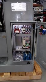
LCM-42 Electrical Cabinet with choke.jpg
 
So you just mount the DC bus choke in the VFD cabinet, I do this all the time for the smaller VFDs. Larger VFDs usually have them built into the VFD, but I do not recall seeing this in any under 10Hp. I rarely come across a situation where they are used on smaller VFD installs. A line reactor would typically be a separate enclosure anyway in these smaller systems.
View attachment 229588

Interesting pix..the resistor mounted in your enclosure is a dead ringer for the one I have mounted outside my enclosure.

Regarding some of the posts above, my drive is a single phase IN unit operating in a shop with 240 single phase only and no machines that have any PFC caps. There is a solar array mounted on the roof of the shop and tied into the sub panel feeding same.

Stuart
 
AHA.....

The solar array can have an effect.

First, the power input to the subpanel will have a voltage boosting effect, although those inverters have fairly strict limits on their output voltage, beyond which they shut down. So "local" voltage may be higher than normal line voltage.

Second, it may depend on how good the sine wave filter on the inverter is. if any of the peaks from the inverter (that the inverter puts out but are normally filtered), get rectified in the VFD input, that could "peak detect" and create a higher bus voltage even though the normal line voltage is perfectly acceptable.

It could have much the same result as the PFC caps mentioned earlier.
 
Very interesting. At least I now have something of a lead on this mystery..thanks. I would guess the logical next step could be a small line reactor?

Stuart


Back
Top