What's new
What's new

Home Built Rotary Phase Convert - ground vs neutral help

joey2point0

Plastic
Joined
Oct 15, 2018
New here! Very excited to join to the community. I recently completed my rotary phase convert and WOW! for not ever fiddling with 3 phase before im impressed with how smooth it went, minimal problems and all. Props to Fitch W. amazing instructions!

Im having a hard time grasping this neutral and ground debacle, here is what I have (my brain is a giant list so bear with me):
*220v single phase extension cord that my control box plugs into, it is 6 gage 3 wire(im assuming hot,hot,neutral)
*Neutral is only used to for indicator light inside control box and properly isolated
*3 phase out is a 8g gage 4 wire cable (L1,L2,L3,ground) no ground connected...YET

Do I simply tie the control box frame, motor frame, and 3phase device frame together as a common ground or is the 220v neutral wire incorperated in this as well?
 
Neutral, and the equipment grounding conductor ARE NOT one and the same, and shouldn't be used as such.

Your supply cable should have a green equipment grounding conductor. This green should bond your control enclosure and the motor frame. It should NOT power any indicator lights or control coils.

If you need 120V for your lights and controls, you need to either add a neutral (white) conductor in your supply source cable or add a control transformer from 240 to 120V.

Using 240V indicators and controls will eliminate the need for a neutral connection or transformer.

SAF Ω
 
*220v single phase extension cord that my control box plugs into, it is 6 gage 3 wire(im assuming hot,hot,neutral)
Stop there. You have some detective work to do. You EITHER have two hots NO neutral but a ground, rather, ELSE you have a VERY long obsolete ungrounded outlet with what you SAID you have but probably do NOT have, Eg: both legs and Neutral but NO ground. You MUST have a ground in there. Or add one.

First order of business is to go and find out what you REALLY have.

Not legal and not smart to power even an indicator light, leg to ground. Go and find a 220/250 V one you can put across the legs.

OK to power an RPC with no Neutral. It "becomes" Delta, so is not permitted to pass the line-side's Neutral through to the load side in any case.

I'll let others explain Delta output side of RPC and the option of corner-grounding, as I am not "a believer" in it.
 
Took a look this morning inside the 3 prong plug receptacle and it looks like whoever wired it tied the neutral and ground wires together. From what I gather from above this is not right nor safe. The issue is that the extension cord I built some time ago is only a 3 wire so if I want all 4 lines I would have to replace the 15' cord and plugs...not cheap.

If I were to go this route what would the neutral be used for in terms of my RPC? Right now I only use it for the indicator light and that will soon be removed as you caution against this.

Seriously, your going to come on here and bitch about the price of 15' of cord to do something right as opposed to half assed? Get real.
 
Took a look this morning inside the 3 prong plug receptacle and it looks like whoever wired it tied the neutral and ground wires together. From what I gather from above this is not right nor safe. The issue is that the extension cord I built some time ago is only a 3 wire so if I want all 4 lines I would have to replace the 15' cord and plugs...not cheap.

If I were to go this route what would the neutral be used for in terms of my RPC? Right now I only use it for the indicator light and that will soon be removed as you caution against this.

Lost me on the "not cheap".

The only approved substitute for PROPER wiring, outlets, power cords is "dry air".

IOW do it right or not at all!
 
Larry and thermite, I didn't realize you cared so much about my well being. Thanks?

What I am trying to get at is if the neutral wire is not needed in the RPC I would disconnect it from the outlet and eliminate it from the RPC circuity(120v indicator light and run hot,hot,ground cable. Grounding the control box, motor frame and tool frame.

Good to hear you were either in agreement all along or actually listening after all.

Yes you need that ground. No the RPC doesn't need the Neutral.

And no, whomever bonded the two anywhere but the service ENTRANCE loadcenter was wrong to do that.

DO look and see that you actually HAVE a ground the entire route leading INTO that box where he did the dirty, though. Lack of a ground run TO it may have been why the fiddle was done IN it.

There may be "surprises" under roof anywhere, but the risk has just gone up under your roof as you have detected evidence of the S4B fungus.

My previous owner, for example, cut-in four runs of shiney-wood cable when stretching for an extension, then spliced copper runs, both ends of each so it didn't show-up in the loadcenter. Improper splice technique. Wrong alloy of shiney-wood, too. Serious case of S4B, that was. And yes, or course I found more pockets of it once I knew I had to look.

:(
 
Are you plugging it into a three prong dryer outlet? Those are/were wired with no ground.
I suspect the reason the ground a neutral were connected at the outlet is the bare wire was mistakenly connected to the grounds in the panel. To get the dryer to work it needed neutral so instead of moving the bare wire to where it belonged on the neutral strip (with all white wires) they jumped it at the outlet connection. Three wire dryers are grounded through the neutral wire, which is grounded elsewhere in the system.
 
Thank you gentlemen, youve gotten me half way there. Did some investigating and here are some pictures of what I found:
20181016_171144.jpg
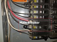
This is the main 40A breaker feeding the garage plug

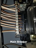
20181016_171159 - Copy.jpg
It looks like all of the grounds and neutrals are tied together in the main breaker panel

20181016_171610.jpg
This is the plug that is in the garage, which my extension cord plugs into. Notice the ground and neutral are tied together like I stated earlier.

20181016_171824.jpg
This is the extension cord that I am using.

Am i still okay to disconnect the neutral and only use the two hots and ground?
 
you definitely don't want the ground and neutral tied together on the outlet. Your first post you say neutral is for an indicator lamp. Well you don't want the back side of that running through ground, either. Since this was wired up by someone who's totally clueless, I would seriously recommend having a real electrician check it all out. No telling what atrocities may be hiding around the corner.
 
I am pretty sure that the only place the ground and neutral should be connected is at the main panel. (and also any isolated sub panels being fed with no ground wire ran with the two hots and neutral)
 
"Atrocities hiding"..... LOL, except it is not actually funny.....

I have found some good ones.

Need an outlet for a hotplate over in the dining room? No problem, run some 14ga aluminum wire from the outlet clear across the basement to the 40A dryer outlet. Hook the ground and neutral together,won't make no difference. While you are at it, put a couple of 120V outlets on the side of that, them things is always handy........

When connecting up a new ceiling fan, just wrap them wires together, and git a few layers of scotch tape on it. Jest as good as a wire nut.......

Never underestimate the stupidity of a determined Bubba. Once you have seen one issue, best to open all the boxes and look for more, they will be there.
 
The way to make it proper and NEC compliant, is to remove the 3W 50A range outlet and replace it with a 4W 50A range outlet. Then you will have a separate connection point for each wire. Nothing left disconnected in the outlet.

Then on your 3W extension chord, replace the 3W connector with a 4W connector that matches the new outlet. On your 3W cable, attach the grounding conductor to the ground prong terminal, and nothing to the neutral terminal. Problem solved.

Its perfectly legal to have the neutral and grounding conductor attached to the neutral bar in the main service panel. But downstream from the main service panel, they are never allowed to be connected together again.

Neutral is for carrying operating current in normal operation. A typical RPC has no need for a neutral connection.

Grounding conductor is to be used only for short circuit currents and keeping everything conductive and exposed, at the same ground potential.

SAF Ω
 
In your first picture how come there is a white wire connected to the bottom breaker?
 
OK to power an RPC with no Neutral. It "becomes" Delta, so is not permitted to pass the line-side's Neutral through to the load side in any case.

I'll let others explain Delta output side of RPC and the option of corner-grounding, as I am not "a believer" in it.

I think that you should take a look at that statement, regarding the output of a RPC.

Your 1Φ residential supply is typically supplied as a center tapped 1Φ. With the center tap as the common (neutral) and grounding conductor reference.

Once it passes through the RPC motor windings, it becomes a center tapped delta, with the addition of the generated leg. You still have neutral and the grounding conductor as a reference point to the original supplied 1Φ. The RPC idler motor windings do not change that reference, as can be proved by the 208V measured from ground or neutral to the generated leg.

Passing a neutral through the RPC controls, to the connected load, will cause no issues, as long as its not used in conjunction with the generated leg. The neutral can still be used for downstream loads with the two utility legs with no problems.

As to corner grounding the RPC center tapped delta output. That is not possible, without causing a short circuit. With either of the utility supplied legs corner grounded, that's a line to ground fault. If you grounded the generated leg, you would still have a fault, but with the added impedance of the motor windings.

There is no reason to "believe in" corner grounding the output, its just not possible with a standard RPC. You would need to add a isolation transformer to the output, in order to be able to corner ground it, if that were desired.
You need the isolation of a transformer in order to derive a different ground reference.

If you were going to add a isolation transformer, it would be much better to derive a wye output, and ground the center point for symmetry to all legs.

SAF Ω
 
Who wired that receptacle? It looks like a 7-50. Can you confirm?

The right outlet would be a 14–50 if you want the neutral. You could pick this plug and outlet up at most big box stores for about $15 apiece. Get the neutral off the ground wire. Get the proper wiring device.

Only at the first distribution centre can neutral and ground be attached. After that it is not allowable.

Nothing is cheap when you go to three-phase (outlet/plug) wiring devices.
 
In your first picture how come there is a white wire connected to the bottom breaker?
I asked myself the same thing when I opened up the main breaker, I'm not quite sure what it is connected to but the breaker wasn't turned on and I don't have it labeled like the others. It will remain off until I have some time to investigate, One atrocity at a time.

Who wired that receptacle? It looks like a 7-50. Can you confirm?
Was wired by a buddy that at the time had light years more electrical knowledge than I did, the tables seem to be turning though. The receptacle is a 10-50

Once it passes through the RPC motor windings, it becomes a center tapped delta, with the addition of the generated leg. You still have neutral and the grounding conductor as a reference point to the original supplied 1Φ. The RPC idler motor windings do not change that reference, as can be proved by the 208V measured from ground or neutral to the generated leg.
We are opening up a whole can of worms that I was not prepared for. I suppose I should explain the whole reason for my RPC build. I bought a old (1991) GM Fanuc Arcmate in supposedly, working when removed, condition. I paid a very reasonable price for it so I am not utterly concerned if it doesn't work (I also have a spare for parts). What I am trying to avoid is being the reason for its demise by giving it the wrong power. Is the difference between delta and wye something that could potentially damage the controller?

Side note I just finished balancing the legs and the largest voltage difference I have is 4 volts between L1 and L3(GEN leg) should this be enough?
 
The bottom breaker with the black and white attached is feeding a 240 volt load, I suspect.
It should either have been wired with black and red, or, as is often done, the white
wire should have been tagged with black tape to indicate it is no longer a neutral.


Back
Top