What's new
What's new

Hot wires, Metal shear, RPC....Need help or advice

Blazer66

Plastic
Joined
Mar 9, 2020
Long time lurker, first time poster.

Recently I added some equipment to my home shop. 17 ton Diacro press brake and a 52-12 hydraulic metal shear.

I have a 30hp RPC that has always run my mill just fine. Installed a 3 phase panel to add machines. My press brake and mill are hooked up and running fine. Bump started the shear to check motor direction and the 12 gauge wires feeding it heated up very hot, seal tight conduit was smoking. Disconnected and rewired with new wires, Started up and ran fine. After sitting for a few days I started the converter to turn the Brake on and the wires feeding the shear heated up again (Shear was not turned on). As hot as the wires were it did not trip the breaker.

We've tested voltages, transformer and starter with no positive diagnosis. Polyphase is not on the transformer.

What would be causing such a power draw that it would heat up the wires without tripping the breaker?

Starter is a Telemecanique # A203B.
 
I'd start by getting an Amprobe on the motor leads as a first step. Suspecting your motor is probably on it's way out. High amps or an imbalanced load leg to leg will help indicate this.
 
We've tested voltages, transformer and starter with no positive diagnosis. Polyphase is not on the transformer.

What would be causing such a power draw that it would heat up the wires without tripping the breaker?
What is the xformer for ?
 
Possible short circuit somewhere? A grounded hot wire will turn instantly hot. Hot as in carrying current, then hot as in warm.
 
What would be causing such a power draw that it would heat up the wires without tripping the breaker?

Without knowing exactly your situation and where the breaker is I would remind you that a breaker upstream from burning wires is a worn breaker.
And you might want to re-check wire size gauge as long as you are replacing wire.

I recently replace a two pole 100A disconnect switch for 230V. One side did not connect so some outlets had 115V and others did not.
This stuff wears out.
 
You have only provided "teaser" information. We need better info, with numbers, or it is all guessing.

What is the breaker rating?

What is the wire size from it?

What is system voltage? presumed 230V, as that is the most common, if not, what is it?

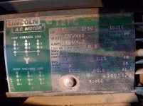
What is the motor power? If possible pic of motor data plate.

Is the motor for-certain connected for the available voltage?

Are you sure power is getting to the motor on all 3 wires? (no opens, etc)

What current are you getting in the wires to the motor when and if it is running OK?
 
Breaker rating is 3 pole 20a. 12 gauge wire to machine. System voltage is 230.
Motor is wired for 230 (low voltage)
Motor starter appears to be in good working order.
Going to test power to motor wires today.

Tech guy from manufacturer suspects motor starter may not be unlatching completely. Possible weak coil in starter?

It's a bizarre condition, never experienced anything like this before. Having trouble uploading pic, may have to resize and try later.
 

Attachments

  • shearmotor.jpg
    shearmotor.jpg
    92.4 KB · Views: 55
It dawned on me as soon as I posted the motor tag pic.
My individual line voltages are L1-118, L2-118, L3(manufactured leg)-204.
I don't believe this motor will run like that.
Am I thinking correctly?
 
Check that you have symmetrical voltages phase-to-phase. To ground doesn't matter because you're not connecting any windings to ground.

Check that the motor wire numbers are connected per the diagram, and do not connect a neutral to the motor.

Check that there's nothing loose or bare that could vibrate into something else, or vibrate loose.

With either the power or motor disconnected, check that all poles of the contactor open and close when they should.

Check voltages with the motor running, and that it's drawing symmetrical current on each leg.
 
It dawned on me as soon as I posted the motor tag pic.
My individual line voltages are L1-118, L2-118, L3(manufactured leg)-204.
I don't believe this motor will run like that.
Am I thinking correctly?


Those are voltages to the neutral of a high-leg system You want to measure line-to-line, which will likely be fine, given those numbers..

You need to look at the motor controller. The contactor may not be releasing all lines, which seems to be what your tech suspects as well. In that case, the motor will most likely also be getting warm as well it may be still "single-phased" even though the contactor should have released.

Voltages are fine, contactor working properly, went through all of that with an experienced friend. The one thing we did discover is I may have a capacitance problem in my RPC, it does have some age.
One leg on my shear is pulling darn near 9 amps at idle, press brake the same. Jumps over 15 when shear is activated.
If I replace the capacitors and still have this same amp draw problem on one leg it may be time to look into a VFD. Last thing I want to do is hurt one of these motors.
 
Check that you have symmetrical voltages phase-to-phase. To ground doesn't matter because you're not connecting any windings to ground.

Check that the motor wire numbers are connected per the diagram, and do not connect a neutral to the motor.

Check that there's nothing loose or bare that could vibrate into something else, or vibrate loose.

With either the power or motor disconnected, check that all poles of the contactor open and close when they should.

Check voltages with the motor running, and that it's drawing symmetrical current on each leg.

Voltage phase-to-phase are 240, 220, 240. Motor wires are connected per the diagram. No neutral to motor.
Disconnected motor from starter and opens and closes as it should, also voltages phase-to-phase are equal from line side as where the motor connects.
Using an amp meter, L1 is pulling 9 amps at idle, spikes to 15+ when shear is activated. The other 2 legs are way lower in amperage, L2 is just below 5 amp and L3 (manufactured leg) barely pulls any.
All 3 of my machines hooked to this converter show the same results.
Could this be a problem with my converter or the capacitors?
 
The interesting thing about 3 phase is that the amps need to add up, at least roughly.

You have 3 wires, so what is flowing on one wire MUST return on another... or as is usual, on a combination of them. Then on average, with a balanced system, all wires should have the same current. Most regular current meters read an average, some read "rms". RPCs tend not to be perfectly balanced, so the currents may not balance either. Generally they are not that wildly unbalanced, however.

If one leg truly has high amps, then those must return on other wires. Either on the two other power wires, or on the grounding conductor.

A quick way to determine if there is any conduction on the grounding conductor, aside from clamping the meter on it, is to put the clamp around all three load power wires at once. That should read zero.

Your idle current of 9A is too high, one would expect perhaps 4 or 5 A. BUT, WHERE ARE YOU MEASURING?

You need to measure on the actual wires going to the load motor. Measuring at the RPC motor can include other currents that are internal to the RPC and not relevant to the load. That would almost certainly give unbalanced readings.

You at one point mentioned having warm wires when the load motor was actually disconnected, or at least that was what it seemed you said. The only ways for that to happen are if you are not measuring on the actual load wires, OR there is a problem with the load (it is not actually disconnecting, etc).

Something is not quite "adding up" here.

Ok, let me try to explain a little better. It's always easier to test things when no one else is around.
I just ran out and bought a new meter with amp clamp (Kiein CL380)

Out of converter (lugs in 3 phase panel)
1-2 = 244v
1-3 = 221v
2-3 = 250v

Voltage at input of starter
1-2 = 244
1-3 = 220
2-3 = 250

Amp Clamp on motor wires machine (machine is idling but hydraulic pump does make some pressure)
1 = 10a
2 = 4.4
3 = 7

Amp clamp around all 3 motor wires reads 0

Amp clamp on motor wires actuating hydraulics (spike at bottom dead center after sheet metal is sheared)
1 = 18
2 = 9
3 = 18

I wish I knew the technical terms to better explain it. What I'm worried about (suggested by an experienced person) is, are these draws too high and could cause damage to the motors?
Im paranoid since it smoked the wires and didn't trip the heaters before I rewired it.
Since then It seems to be starting and operating fine.
20200311_153103.jpg
 
Last edited:
The motor is rated 8.4A, continuous, with an allowance for overage. You are seeing 18A on two wires, which I presume are actually the "straight through" wires, although the wire numbers do not show that consistently.

The machine is a shear? So I am assuming the high current is, as you say, a spike as the shear finishes the cut. It may be that there is "some" of what I would call "intentional overloading" involved. I would NOT expect it to be that much.

The fact that it is on two wires seems to show that the RPC is not contributing as much as it ought to. But the wire numbers are confusing.

I would normally expect the generated leg (coming only from the idler) to be the one with the low current, which would be wire #2 per the last two readings (4.45A and 9A).

QUESTIONS: Are the wire numbers you give the same for all readings? Which one is actually the generated leg?

I would expect that the motor, if there is an intentional overload, to be running at, say, 8A, and have a maximum of something like 12A or so, maybe a bit more, during the overload. The 18A is a bit higher than I would expect.

That said, a short overload during the stroke of a bending brake or shear is not out-of-line. And it will not overheat anything if it is not extended, and is a fairly small portion of the cycle. Myself, I would prefer that it was more evenly balanced, but.....

The way a shear etc operates, the overload might be 10% or less of the time, because there is time lining up the material, etc, and the stroke is just a short time.

QUESTIONS: I think you bought an American Rotary, rIght? Did you supply the idler or was it a package?

If you supplied the idler, was the rest of it a type that covers a range of idler sizes, and you are supposed to adjust it for your idler? Was any adjustment done?

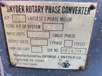
My RPC is a Snyder converter, was rewired/rebuilt a bunch of years ago as well as sat on a shelf for a bunch of years too. I didn't do anything more than wire it up, turn it on and check the voltages.
This is starting to lead me to believe that the converter isn't performing the way it should as the low amp draw line (generated phase)shows the same on all 3 machines.

Sorry if my wire numbers were confusing.
T1 and T3 have the "straight through" wires.

Amp draw on shear motor wires running but not cycling shear.
T1 - 10.0 amp
T2 - 4.4 amp (T2 is the generated leg)
T3 - 7.0 amp

The numbers above are identical on the press brake as well, which has virtually identical motor specs.
I thought it would balance out better as more machines were turned on but it doesn't make a difference.

If it is an RPC problem, how would I go about testing it to help me make up my mind if I should abandon the RPC and install VFD's.

Phaseconverter.jpgPhaseconverter.jpg
 
Test #1.... does RPC draw more than 5A when there is NO load on the output?

Test #2... What is voltage from RPC with NO load on the output?

question: does the RPC have "run", or "balance" capacitors in it? They would be several metal cased capacitors that are connected directly across output lines, from the "pass through" lines to the generated leg. NOT connected through any relay etc.

There are probably also some capacitors, either metal or plastic cased, that are connected through a relay as well (start capacitors). Not every RPC has a relay, mine has a permanently connected capacitor bank that serves as both start and run capacitors.

Yes it's pulling more than 5 amps from the single phase double pole 100 amp breaker that feeds it. pulling 11 amp and 7 amp. (no output load, just idling.

Voltage from RPC with no load on output.
1 to gnd = 122.1
2 to gnd = 121.3
3 to gnd = 202.4 (generated leg)

1-2 243.6v
1-3 221.3
2-3 250.1
(3 being the generated leg)

There's a total of 5 capacitors. I don't really know which is which.
3 tall metal ones and 2 round plastic ones. (see attached pic)
Don't mind the mess inside the box, that's how I inherited it.


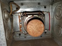
No relays, has a centrifugal switch mounted on output shaft of motor. (see attached pic)


Capcitors.jpg

ConverterStarter.jpg

Capacitor1.jpg


Back
Top