What's new
What's new

how critical is brushed dc servo voltage spec?

tomjelly

Stainless
Joined
Aug 26, 2007
Location
GA
I'm doing the planning to put a new control in a machine I just got here, it has a 220v 3 phase spindle that runs on a 200-230v VFD. It has 140v 8.6A SEM DC brushed servos. It has a 2kva primary 240x480 secondary 120x240 transformer feeding the servo drives with no further step down from the simple (capacitor and rectifier only) power supply on board the servo rack. I know that this machine was previously running on 240v via rotary phase converter before I got it. The resultant voltage to the drives measures 171v; makes sense because theoretically recified 120vac x 1.414=170vdc. From what I've read you are supposed to feed these motors less than their rated 140vdc, so I'm assuming I should use a 2kva transformer with 100v or slightly lower out to run this, correct? or are the drives able to handle that voltage & protect the motors from over voltage (because they have been running like that)? either that is the case or POSSIBLY the machine was originally spec'd to run on 208, but even that into the transformer would result in 147vdc

Can I run with this PSU or do I need to buck to under 100vac input?
 
..resultant voltage to the drives measures 171v; makes sense because theoretically recified 120vac x 1.414=170vdc.

That - the input - is only the first one-third of the calculations needed.

Next is whether half-wave or full wave rectification.

Next is the filter. R or L PLUS C, C alone, or some combination, and if so which one is encountered first.

And then ... you may not be reading what you think your are reading with your meter, either.

All those basics are online, many places.

And "Servo rack" as well as "servo motor"?

That implies .. to me at least - control bridge or amplifier - and the effect on output - not just "transparent" wire and switches.

Can we see a schematic - whole shebang?
 
Why not tellus what the machine is and what the original servo amps are so we can guess what was going on previously. The input to the servo amps is not what the output is.

And yes I think your assumption is correct that the output to the servos should be lower than the rated voltage
 
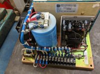
There is no schematic available, but its pretty easy to see the wiring in the photo. power comes in on the terminal strip, bottom. 1 power lead goes to the rectifier behind the fuse, lower left, the other power lead comes off the fuse and goes again to the rectifier diagonally opposite the other. The DC wires come off the rectifier to the 5400uf 200vdc cap and go directly to the drives, servo dynamics SDFPO1525-17. The drives have been superseded by a newer model, the only diagram I've found is here:
SDFPO1525 Servo Amplifier - Servo Dynamics
its from a Standard Router brand 4'x4' router. Motors are 3 servo dynamics mts30m4-38, 26 in/lb 8.6A 140v
I'm reading dc volts from the teminals on top of the cap...rack is supplied from the transformer in photo 2. the cooling fans are 115v
 

Attachments

  • 2020-03-09 13.01.00.jpg
    2020-03-09 13.01.00.jpg
    96.9 KB · Views: 59
  • 2020-03-09 12.59.38.jpg
    2020-03-09 12.59.38.jpg
    83.5 KB · Views: 46
I'm not assuming the builder had it wrong, as I stated in the OP if it was originally intended for 208 or had a different supply transformer its quite possible that the power supply output would have ended up under 140v, I just know that it was running on 240. my question is more do servo drives generally limit voltage from a power supply that exceeds the motor voltage rating so it is OK to have a higher supply voltage.
 
I'm not assuming the builder had it wrong, as I stated in the OP if it was originally intended for 208 or had a different supply transformer its quite possible that the power supply output would have ended up under 140v, I just know that it was running on 240. my question is more do servo drives generally limit voltage from a power supply that exceeds the motor voltage rating so it is OK to have a higher supply voltage.

I think you are over thinking this.

There is a voltage drop across all transistor circuits. The builders of the servo amp knew this and specifically chose all of the components including the motors to fit the design criteria.

In addition to this, the servo motor voltage is going to be a function of acceleration and the mass the servo is moving.
 
I'm not assuming the builder had it wrong, as I stated in the OP if it was originally intended for 208 or had a different supply transformer its quite possible that the power supply output would have ended up under 140v, I just know that it was running on 240. my question is more do servo drives generally limit voltage from a power supply that exceeds the motor voltage rating so it is OK to have a higher supply voltage.

A DC Drive - or a servo amp - not identical, but close-enough cousins with a degree of overlap, some applications can use either one - is akin to an automatic transmission in a motor vehicle - or the valve on the spigot to your your sink or shower. IOW it throttles power with a high degree of finesse.

Same again AC servos. See "H" bridge for simple - or think VFD with finer control ..it can get complex. Or be brute simple. See MIM-14B, NIKE Hercules control system. "Hollow State".

These NEED more input power - for reserves - than they usually deliver, even at "full throttle" or "slew" rates AKA "rapids".

A switch, OTOH? Like a dog-clutch. Or the trigger on a firearm.
No subtlety, no "partial" delivery", no shades of grey.

Activate one of this class? BANG! You get all there is, and right NOW!

NB: Firearms don't even have "reverse".

Thank God in her infinite wisdom!

:)


Back
Top